Software Engineering Course Note
Made by Mike_Zhang
Notice | 提示
个人笔记,仅供参考
PERSONAL COURSE NOTE, FOR REFERENCE ONLYPersonal course note of COMP3211 Software Engineering, The Hong Kong Polytechnic University, Sem1, 2022.
本文章为香港理工大学2022学年第一学期 软件工程(COMP3211 Software Engineering) 个人的课程笔记。Mainly focus on Software Processes, Agile Software Development, Requirements Engineering, System Modelling, Architectural Design, Object-Oriented Analysis and Design, Software Testing, Software Evolution, and Software Reuse.
Unfold Software Engineering Topics | 展开软件工程主题 >
0. PDF Version of the Note
[PDF] Software Engineering Course Note
1 Reference Book and Solutions Manual
[PDF] Sommerville Software Engineering 10ed
[PDF] Solutions Manual of Sommerville Software Engineering 10ed
2 Software Processes
Definition:
A structured set of activities required to develop a software system.
Including Activities:
- Specification: what the system should do, and the goal;
- Development: Produce the software meets the specification;
- Design;
- Implement;
- Validation: Check whether it does what it should do;
- Evolution: Change the system as response to the changed needs;
2.1 Software Process Descriptions
Including:
- Activities:
- data model,
- designing user interface,
- as well as their orders.
- Products(deliverables): the outcome
- of the process activities;
- Roles:
- People in the activities;
- Pre and Post conditions:
- process only starts when the pre. is satisfied
- e.g.
float sqrt(float x): - Situation1:
- x>=0 is the pre.
- return value(r, r^2 ~= x) satisfied the post.
- Situation2:
- pre: True;
- post: x>=0: r^2 ~= x / x<0: exception
2.2 Two Types of Processes
2.2.1 Plan-Driven Process
All activities are planned in advance, progress is measured against the plan
2.2.2 Agile Process
Planning is incremental, easy to change the process.
Has plan, but NOT a plan for the whole process.
2.3 Software Process Models
An abstract representation of a process with description of a process.
2.3.1 Waterfall Model
Plan-Driven;
Separate and Distinct 4 activities;
- Specification: Requirements analysis and definition;
- Development: System and software design;
- Validation:
- Implementation and unit testing;
- Integration and system testing;
- Evolution: Operation and maintenance.
Benefits:
- Advantage: visible to management people, easy to understand;
Drawbacks:
- No back way until the last step, a phase must be completed, hard to change;
- Only appropriate:
- when being sure no change in the future (well-understood);
- or change has little influence (changes will be fairly limited);
- Examples:
- Embedded systems:
- requirement is fixed;
- Critical systems:
- whole check/design will be done before development less likely to have large changes
- Large software systems:
- interface/connection between several partner companies is fixed before -> not easily to change
- Embedded systems:
2.3.2 Incremental Development
- Developing an initial implementation;
- Getting feedback from users and others;
- Evolving the software through several versions until the required
system has been developed
- Plan-driven, agile or, mixture of these approaches;
- No need to deliver each increment to the system customer;
Benefits:
- The cost of changing is less;
- Easy to get feedback from customer;
- Fast to delivery and deploy, as one of the versions may satisfy the requirement, finished earlier;
Drawbacks:
- Process is not visible;
- Developing several requirement at a same time, not one by one, which is not invisible to the manager, who does not know the true progress;
- Structure tends to degrade as new increments are added;
- Documents may change time to time for each update;
- Former structure based on the former requirement may NOT be suitable for later requirement, which may need to degrade the structure.
2.3.3 Integration & Configuration
- software reuse;
- systems are integrated from existing components or application systems;
- application systems: to configure;
- components: to adapt
- Example:
- Stand-alone application systems;
- Package, framework;
- Web services;
Benefits:
- Reduced costs and risks as less software is developed from scratch;
- Faster delivery and deployment of systems
Drawbacks:
- Requirements compromises are inevitable so the system may not meet the real needs of users;
- Loss of control over the system evolution;
2.4 Process Activities
Real software processes are inter-leaved sequences of technical, collaborative and managerial activities
The four basic process activities:
- Specification;
- Development;
- Validation;
- Evolution
2.4.1 Software Specification
- Services requirements;
- Identifying the constraints on the system’s operation;
Step for Specification:
- Requirements elicitation(extraction) and analysis;
- require or expect;
- Requirements specification in detail;
- Requirements validation: Checking;
2.4.2 Software Development
Process of developing an executable system for delivery to the customer.
Activities of design and implementation are closely related. They may be separate or inter-leaved.
2.4.2.1 Software Design
Design a software structure.
Architectural design:
- overall structure of the system;
- principal components (subsystems or modules);
- their relationships and how they are distributed.
Database design:
- data structures;
- how these are to be represented in a database.
Interface design:
- where you define the interfaces between system components.
Component selection and design:
- where you search for reusable components and, if no suitable components are available, design new software components.
2.4.2.2 Implementation
- Developing a program;
- or programs or by configuring an application system.
Testing: Establishes the existence of defects;
Debugging: Locating and correcting these defects.
2.4.3 Software Validation
Verification and validation (V & V) is intended to show that a system conforms to its specification and meets the requirements of the system customer.
Requirements = user p.o.v. req. + perceived(developer p.o.v.) req.
Verification:
- Check implementation again the the perceived req.(user and system from developer point of view) as internal checking of a developer group;
Validation:
- Check real user req. since perceived req. may be incorrect.
Testing in V&V:
- Component testing (Verification): Testing of individual components;
- System testing (Verification): Testing of the system as a whole;
- Customer testing (Validation): Testing with customer data;
2.4.4 Software Evolution
Software is inherently flexible and can change.
- Requirement changed -> software evolve and change;
- The distinction between development and evolution (maintenance) is increasingly irrelevant as software is continually changed as an evolutionary process in response to continually changing requirements and customer needs.
2.5 Coping With Changes
Change is inevitable:
- Software is in the real world;
- Human make mistake;
The moving target problem: The requirements change while the software product is being developed.
- Any change potentially cause a regression fault;
- Too many changes: redesigned and reimplemented;
- No solution to the moving target problem;
2.5.1 Reducing The Costs of Rework
Change anticipation (beforehand):
- Anticipate (predict) possible changes before significant rework is required.
- prototype can show key features of the system to customers.
- Anticipate (predict) possible changes before significant rework is required.
Change tolerance (quick response):
- Designed so that changes can be accommodated at relatively low cost.
2.5.2 Coping with Changing Requirements
2.5.2.1 System Prototyping
A version of the system or part of the system is developed quickly to check the customer’s requirements and the feasibility of design decisions.
Benefits:
- To help with requirements elicitation and validation;
- Improved system usability;
- A closer match to users’ real needs (get feedback from customer);
- Improved design quality;
- Improved maintainability;
- Reduced development effort (prototype may be reused later directly).
Prototype Development:
- Key is to define the prototype functionality
- Involve leaving out functionality:
- Focus on areas of the product that are not well-understood;
- Error checking and recovery may NOT be included
- Focus on functional requirements like reliability and security, not non-functional;
2.5.2.2 Incremental Delivery
The development and delivery is broken down into increments.
- User requirements are prioritised, and the highest priority requirements are included in early increments;
- Once the development of an increment is started, the requirements are frozen;
- If comes new changed during the loop, it will be considered into the next loop, NO effect on the current one.
Benefits:
- Early elicit requirements for later increments;
- Functionality is available earlier;
- Easy to incorporate changes;
- Highest priority system services tend to receive the most testing.
Drawbacks:
- Difficult to implement for replacement systems;
- Common facilities can be difficult to identify with incremental delivery;
- Spec is developed in conjunction with the software (no full spec);
2.6 Process Improvement
Reason:
Hard to predict the quality of the final software product in the process;
Enhancing the quality of their software, reducing costs or accelerating their development processes.
- Process improvement means understanding existing processes and changing these processes to increase product quality and/or reduce costs and development time.
Ways:
Process maturity approach:
- Improving process and project management and introducing good software engineering practice;
- Leads to increased overhead;
Agile approach:
- Iterative development and the reduction of overheads in the software process;
- Rapid delivery of functionality and responsiveness to changing;
- With the lowest overheads;
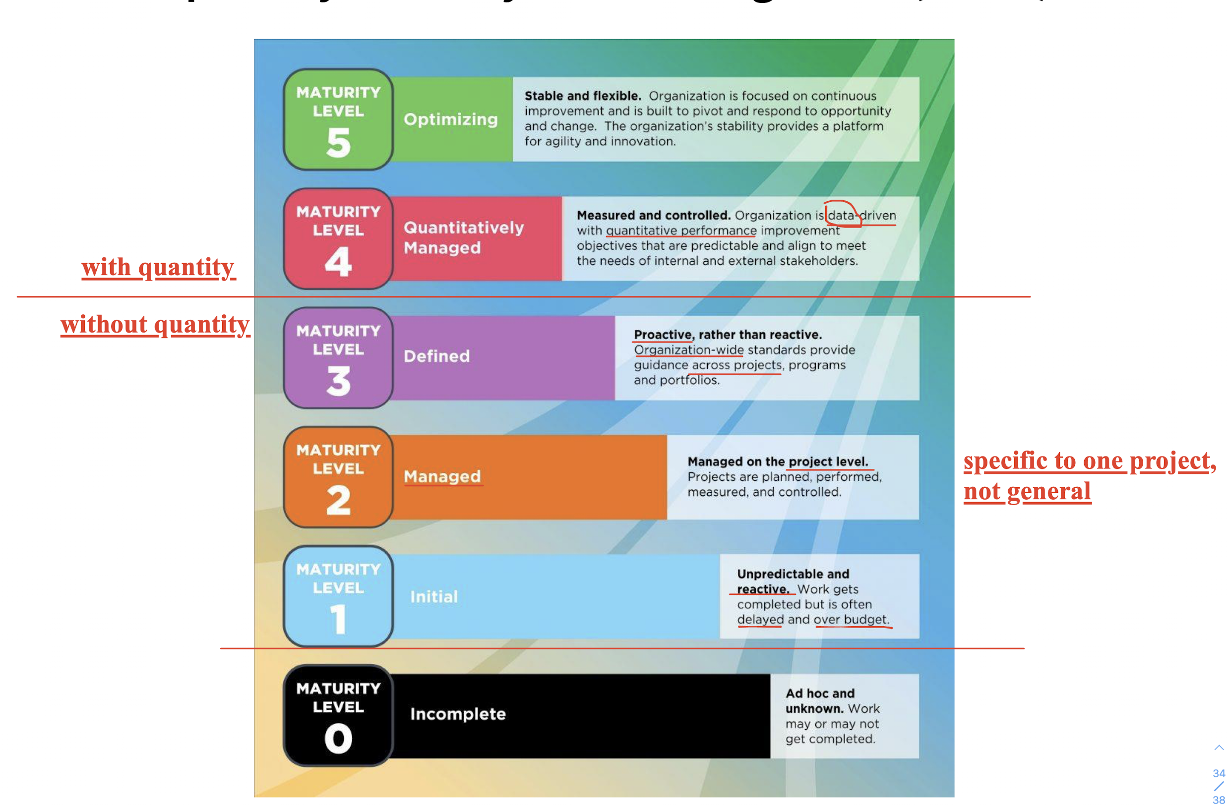
2.6.1 The Capability Maturity Model Integration (CMMI) Model
To improve the maturity
3 Agile Software Development
Agile methods are incremental development methods that focus on rapid software development, frequent releases of the software, reducing process overheads by minimizing documentation and producing high-quality code.
Rapid Software Development
Businesses operate in a fast-changing environment, thus software must evolve quickly to reflect changing, which can NOT be handled by the Plan-driven Development.
Afterwards, the Rapid Software Development becomes Agile Development(Agile Method) .
Common Characteristics of Agile Methods
- Several activities are interleaved;
- Less documentation, more on code;
- Developed in several versions with stakeholder involved in increments;
- Extensive tools, like automated testing tools.
Plan-Driven vs Agile Development
Plan-Driven
- plan-driven and incremental development is possible;
- Iteration occurs within activities in incremental, not in waterfall model
Agile Development
- Activities are inter-leaved;
- Iteration occurs across activities.
3.1 Agile Methods
3.1.1 Aim
- Reduce the overhead (e.g. less documentation);
- Quickly respond to changes with large reworks;
- Focus on Code than design (or documentation).
3.1.2 Agile Manifesto
- Individuals and interactions > processes and tools;
- One people do one activity in their best, easy to change the role without affect other activities;
- But less flexibility;
- Working software > comprehensive documentation;
- Comprehensive documentation: need lot time, and requirement is constantly changing, so do the doc need to be updated constantly, more time needed
- Customer collaboration > contract negotiation;
- Responding to change > following a plan.
3.1.3 Principles of Agile Manifesto
Customer involvement
- Customers should be closely involved for update requirement
Incremental delivery
- The software is developed in increments with the customer specifying the requirements to be included in each increment.
People not process
The skills of the development team should be recognized and exploited. Team members should be left to develop their own ways of working without prescriptive processes.
No task assignment in XP, choice in programmer
Embrace change
- Expect the system requirements to change and so design the system to accommodate these changes.
Maintain simplicity
- Focus on simplicity in both the software being developed and in the development process. Wherever possible, actively work to eliminate complexity from the system;
- No over design, focus ONLY requirement in the next increment.
3.1.4 Agile Method Applicability
- NOT for large project, only for a small or medium-sized product;
- software products and apps;
- Custom system development within an organization;
- Easy to involve customer in the agile method process
- Few external rules and regulations that affect the software.
3.2 Agile Development Techniques
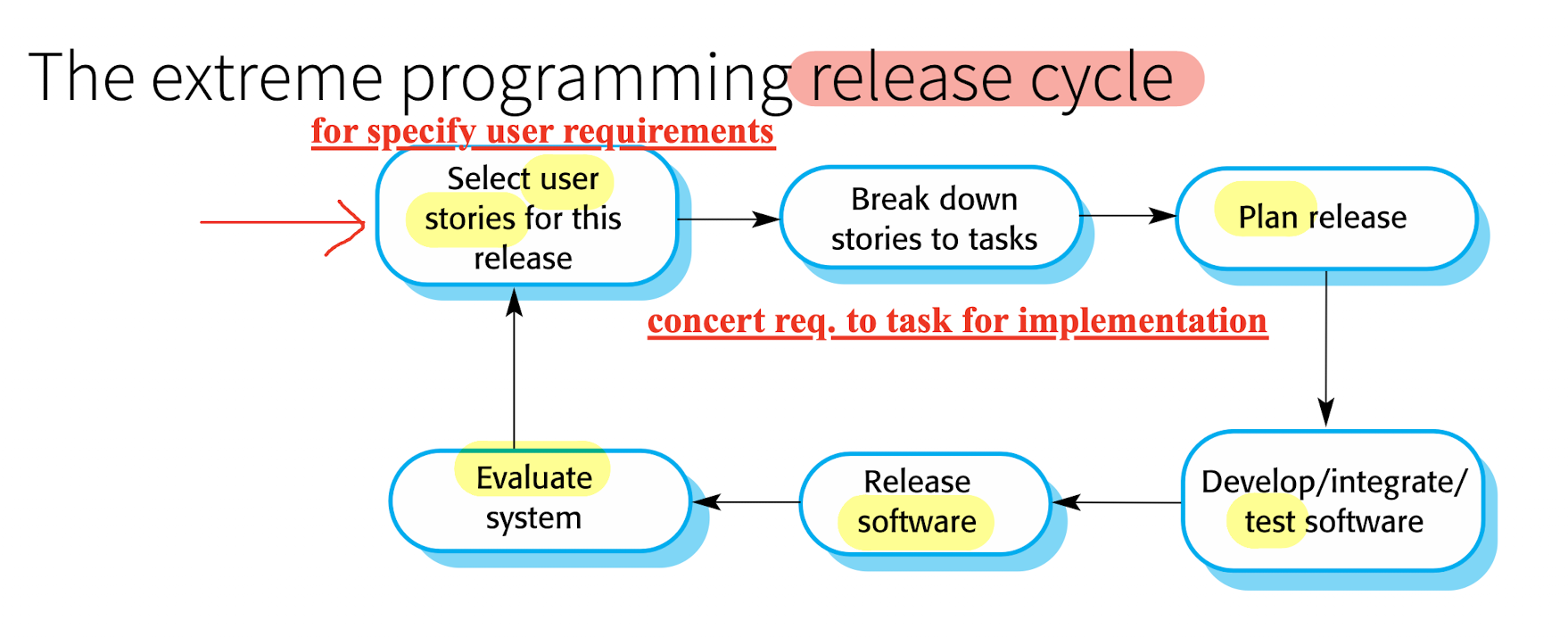
3.2.1 Extreme Programming (XP)
- A very influential agile method;
- Pushing recognized good practice to “extreme” levels, (Good but may not be suitable for company to build for “extreme”)
- Build several new versions every day;
- Deliver increments to customers every 2 weeks;
- Run test for every build and only accept it after passing the test;
- Release cycle:
3.2.2 XP Principles or Practices
- Incremental Planning
- Plan for next release cycle;
- Small Release
- Release per 2 weeks;
- Frequent and incrementally add functionality to the first release;
- Simple Design
- Reach the current req. ONLY;
- NO more extra design(over design) for anticipation, which should be included into the next plan and requirement;
- Test-first Development
- Define test for functions BEFORE the function implementation;
- Refactoring
- the design is changing frequently, so do refactor when change is found;
- It keeps the code simple and maintainable;
- Pair Programming
- Work in pairs, checking each other’s work;
- Collective Ownership
- ALL the developers take responsibility for ALL of the code. Anyone can change anything;
- Easy to refactor, no sorry;
- Continuous Integration
- After any such integration, all the unit tests in the system must pass;
- comb, test, comb, test, comb, test,… , to find bugs as early as possible;
- Sustainable Pace
- NO large amounts of overtime, which will often reduce code quality;
- On-site Customer
- Is responsible for bringing system requirements to the team for implementation.
3.2.3 Map Between Agile Principles and XP Practice
| Agile Principles | XP Practice |
|---|---|
| Incremental development | Small, frequent system releases |
| Customer involvement | Continuous engagement of the customer |
| People not process | Pair Programming, Collective Ownership, and Sustainable Development Process |
| Change is embraced | Regular system releases, test-first development, refactoring, continuous integration of new functionality |
| Maintaining simplicity | Constant refactoring that improves code quality, simple designs that do not unnecessarily anticipate future changes |
3.2.4 Influential XP Practices
Some key practices of XP
3.2.4.1 User Stories for Requirements
- User making decision on requirements;
- But user may NOT have strong technology background;
- So easier to find requirement from users’ stories;
Drawbacks:
- Difficult to judge if enough user stories have been developed to cover all the essential requirements;
- Whether the story is true to not;
- May miss some part in the story for the user is so technological.
User non-technology story -> Tasks
3.2.4.2 Refactoring
- Constant code improvement (refactoring) to make changes easier;
- “Design for change” (anticipation) is NOT worthwhile as changes cannot be reliably anticipated.
Benefits:
- Improves the understandability, less documentation;
- Changes are easier to make for well structure;
Drawbacks:
- Local changes tend to degrade software structure and readability;
- Refactoring sometimes gets delayed;
Example:
Renaming attributes and methods to make them easier to understand.
Replacement of inline code with calls to methods that have been included in a program library.
3.2.4.3 Test-first/Test-Driven development
Testing in XP:
Requiring that program should be tested after every change has been made;
Its features:
- Incremental test;
- Test-first development;
- User involvement in test;
- Use of automated testing frameworks;
Test-Driven development(TDD):
TDD is the in computer language, like JUnit (may in human language but need operated by human);
Test-first development: Tests are written as program BEFORE code;
- Force you to write test;
- Set goal, interface, return value, parameter type.. before head.
Customer/User Involvement:
- To develop acceptance tests for the stories;
- Customer who is part of the team writes tests;
- Drawbacks: customer role have limited time;
Test Automation:
Tests are executable and run automatically when new functionality is added;
Testing components should be stand-alone:
- Each test is independent, without affecting each other;
Program can NOT pass the test, may due to:
- 1.Program has bug; 2.Test is false; 3. Test and Program have bugs
Automated test generation $\to$ Automated test execution $\to$
Automated Program repair (assume T is correct)
Automated Test repair (assume P is correct)
Drawbacks of TDD:
- Programmers do not like to write tests;
- They may take short cut in writing test which may nor cover all cases;
- Tests can be very difficult to write incrementally;
- Like, ‘display logic’ and workflow between screens;
- Difficult to judge the completeness of a set of tests.
- Balance of quality vs. coverage;
3.2.4.4 Pair programming
Programmers sit together dynamically at the same computer to develop the software
Benefits:
- Collective ownership and responsibility for the system;
- Like an informal review process because each line of code is viewed at by at least two people;
- Encourages refactoring;
- Not necessarily inefficient:
- efficient in some way, like beginner;
- Drawback: professional programmer may have less efficiency;
3.3 Agile Project Management
Plan-driven software development:
- Managers draw up a plan for the project;
- software project managers is to manage the project so that the software is delivered on time and within the planned budget for the project.
Agile methods:
- project progress are less visible:
- teams are self-organizing,
- do not produce documentation,
- and plan development in very short cycles.
- adapted to incremental development.
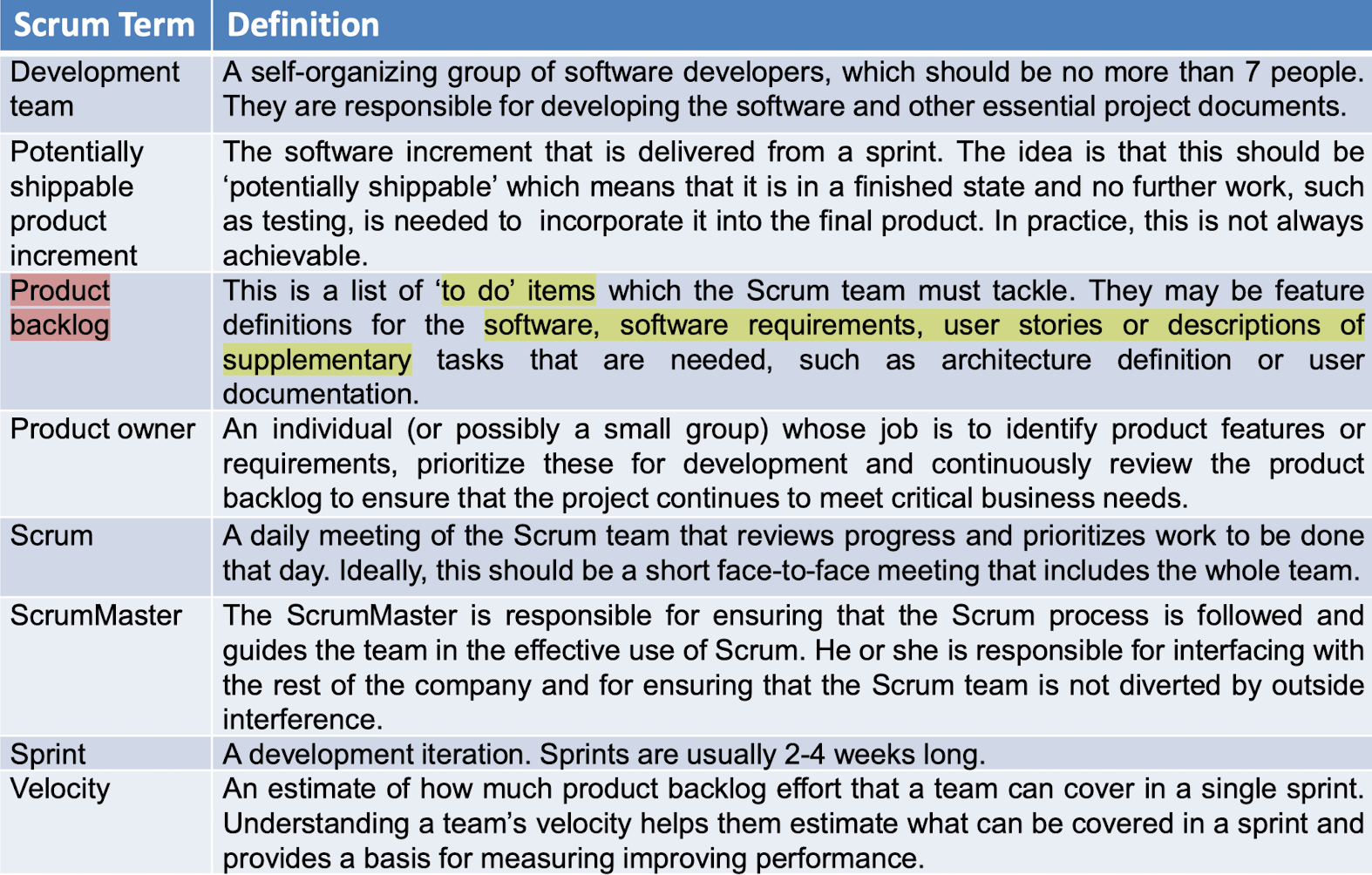
3.3.1 Scrum
An agile method that focuses on managing iterative development rather than specific agile practices.
Three phases in Scrum:
- Initial phase:
- an outline planning phase where you establish the general objectives for the project and design the software architecture;
- Series of sprint cycles:
- Develops an increment of the system;
- Project closure phase:
- wraps up the project, completes required documentation
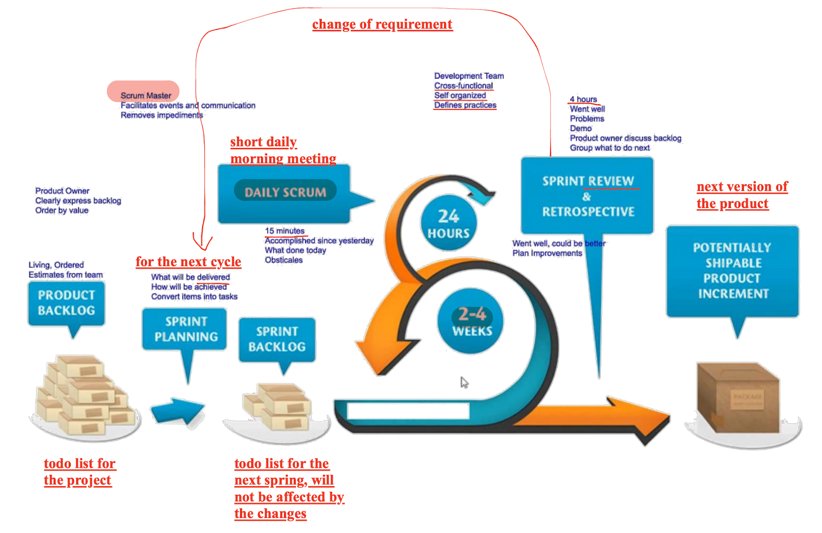
Benefits:
- Unstable requirements do not hold up progress;
- None of changes affects the spring cycle in 4 weeks, only following the spring backlog;
- Whole team has visibility of everything;
- Customers see on-time, gain feedback;
- Trust between customers and developers is established.
Scrum can be scaled to large projects with Multi-Team Scrum
4 Requirements Engineering
Requirements:
- services provided by the system (functional part), and
- constrains on the operations (non-functional)
Requirements Engineering (RE) :
- The process of
- identifying,
- analyzing,
- documenting,
- checking,
- of requirements (services and constrains).
Types of Requirements:
- User Requirements
- The overview without details of the requirements (services and constrains)
- in natural language and diagrams;
- System Requirements
- Structured document with details, implementations of
- functions, services and constrains of systems;
Different kinds of requirements are needed to different types of stakeholders.
Requirements in agile processes:
- May be a waste of time;
- The requirements are changing all the time, so do the requirement documents;
- User stories are used instead of requirements documents, which is the incremental requirements;
In most large systems, there always will be some clearly identifiable requirement engineering activities at beginning.
The outcome of the RE is the requirement document.
4.1 Functional and Non-Functional Requirements
- No clear distinction between functional and non-functional requirements;
- Non-functional requirements may generates functional requirements;
4.1.1 Functional Requirements
- Services provided by the system;
- Reaction to the inputs;
- Behaviors in different situations;
- The type of the software;
- The expected users;
- What should NOT do;
- Should be complete and consistent.
- Functional User Requirements
- The high-level (overview) of the what the system should do;
- Functional System Requirements
- Detailed description of the services provided by the system;
4.1.2 Non-Functional Requirements
- System properties and constrains
- properties: reliability, response time, and storage requirements;
- constrains: I/O device capability and the data representations;
- apply to the system as a whole;
- More critical than the functional requirements:
- may affect the overall architecture of a system rather than the individual components.
- non-functional requirement may generate a number of related functional requirements
- Such as:
- Safety (as non-functional) is more important than fancy functions (as functional)
4.1.2.1 Classification
Product requirements
- Specify that the delivered product
- usability, efficiency (performance, space), dependability, security
The Mentcare system shall be available to all clinics during normal working hours (Mon–Fri, 0830–17.30). Downtime within normal working hours shall not exceed five seconds in any one day.
- usability, efficiency (performance, space), dependability, security
- Specify that the delivered product
Organisational requirements
- Consequence of organisational policies and procedures
- environmental, operational, development(programming languages…)
- Consequence of organisational policies and procedures
Users of the Mentcare system shall identify themselves using their health authority identity card.
- External requirements
- which are external to the system and its development process
- regulatory, ethical, legislative (accounting, safety/security)
- which are external to the system and its development process
The system shall implement patient privacy provisions as set out in HStan-03-2006-priv.
4.1.2.2 Writing
Two parts:
- Goals:
- A general intention of the user, like Ease of Use;
- Verifiable (Testable) :
- Some measure (satisfaction) that can be objectively tested.
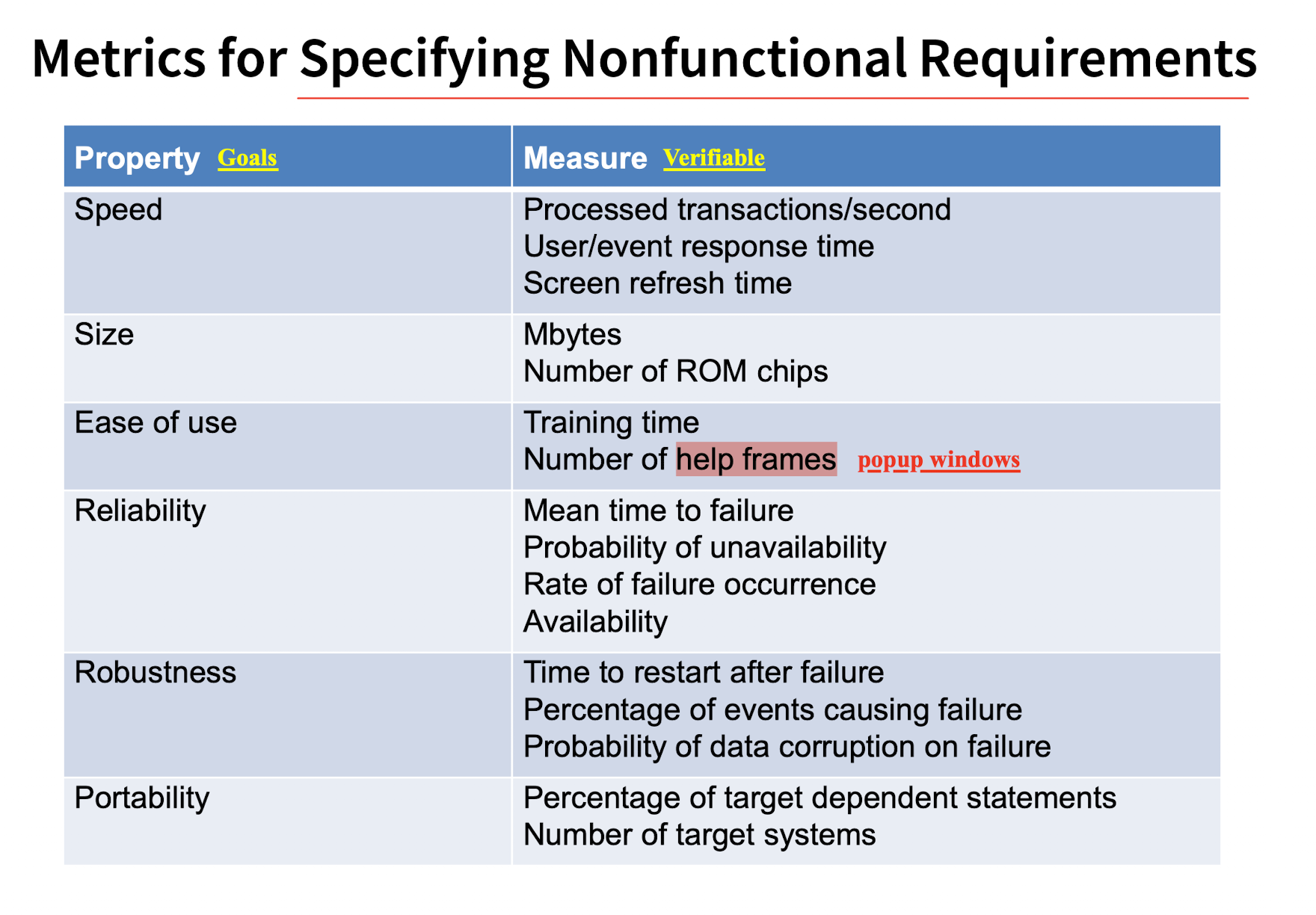
[Example]
Goal:
The system should be easy to use by medical staff and should be organized in such a way that user errors are minimized.
Verifiable:
Medical staff shall be able to use all the system functions after four hours of training (easy to use). After this training, the average number of errors made by experienced users shall not exceed two per hour (minimized) of system use.
4.1.2.3 Challenges
Difficult for customers to translate goals into measurable requirements.
- For no metrics;
- One property may has different measurements which is not clear and may conflict with each other;
- High costs for verification
Conflict and Interact between different functional and/or non-functional requirements;
- efficient vs. maintainable(/safety;
Difficult to separate functional and non-functional requirements
- As many references between functional and non-functional req. difficult to be separated;
4.2 Requirements Engineering Process
- Requirement Elicitation
- Requirement Specification
- Requirement Validation
4.2.1 Requirement Elicitation
AKA. Requirements Discovery
- Working with stakeholders to find out about the application domain, work activities, the services and system features that stakeholders want, etc.
Stages:
- Discovery and understanding:
- Interacting with stakeholders to discover their requirements.
- Classification and organisation:
- Groups related requirements and organises them into coherent clusters.
- Prioritisation and negotiation:
- Prioritising requirements and resolving requirements conflicts.
- Documentation:
- The requirements are documented and input into the next round of the spiral.
The order of them can be changed between activities, as well as cna be selected;
Problems:
- Stakeholders don’t know what they really want (too little or too much);
- Express requirements in their own terms and with implicit knowledge of their own work;
- Different stakeholders, Different requirements, express in Different ways;
- May be influenced by Organisational and political factors;
- Requirements change and business environment may change.
Techniques:
- Interview: talk to people about what they do;
- Closed interviews: pre-determined list of questions
- Open interviews: various issues are explored with stakeholders.
- Problems:
- Not easy to understand user’s language (for Application specialists);
- Interviews are not good for understanding domain requirements;
- Solutions:
- Be open-minded, avoid pre-conceived ideas, be willing to listen
- Suggesting requirements rather than simply asking
- Observation or ethnography: watch people doing their job to see what artifacts they use;
- Benefits:
- People do NOT have to explain or articulate their work;
- Social and organizational factors(laws/rules) of importance may be observed;
- Requirements can be derived from the way that people actually work;
- Requirements can be derived from cooperation and awareness of other people’s activities.
- Benefits:
4.2.2 Requirement Specification
The process of writing down the user and system requirements in a requirements document.
- User requirements:
- be understandable by end-users and customers who do not have a technical background.
- System requirements:
- more detailed requirements and may include more technical information.
- As complete as possible.
requirements: what the system should do
design: how it does this.
- They are inseparable;
Notations for Writing System Requirements:
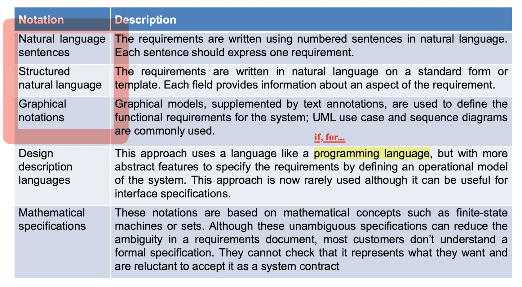
4.2.2.1 Natural Language Specification
- Expressive, intuitive, and universal;
- Potentially vague and ambiguous
- vague: fast, low, large…;
- ambiguous: “The man hit the woman with a stick.”
- Guidelines:
- standard format;
- “shall” for mandatory requirements; “should” for desirable requirements.
- highlighting to identify key parts;
- Avoid the use of computer jargon.
- Include an explanation (rationale) of why a requirement is necessary.
[Example]
3.2 The system shall measure the blood sugar and deliver insulin, if required, every 10 minutes. (Changes in blood sugar are relatively slow so more frequent measurement is unnecessary; less frequent measurement could lead to unnecessarily high sugar levels.)
3.6 The system shall run a self-test routine every minute with the conditions to be tested and the associated actions defined in Table 1. (A self-test routine can discover hardware and software problems and alert the user to the fact the normal operation may be impossible.)
4.2.2.2 Structured Natural Language Specifications
Written in a standard way rather than as free-form text;
Maintains most expressiveness and understandability of NL.
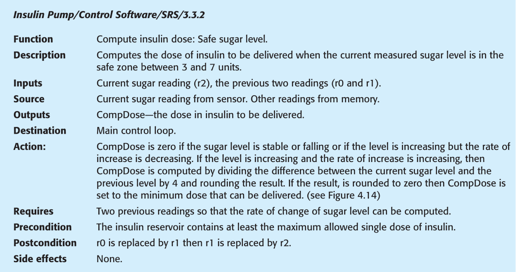
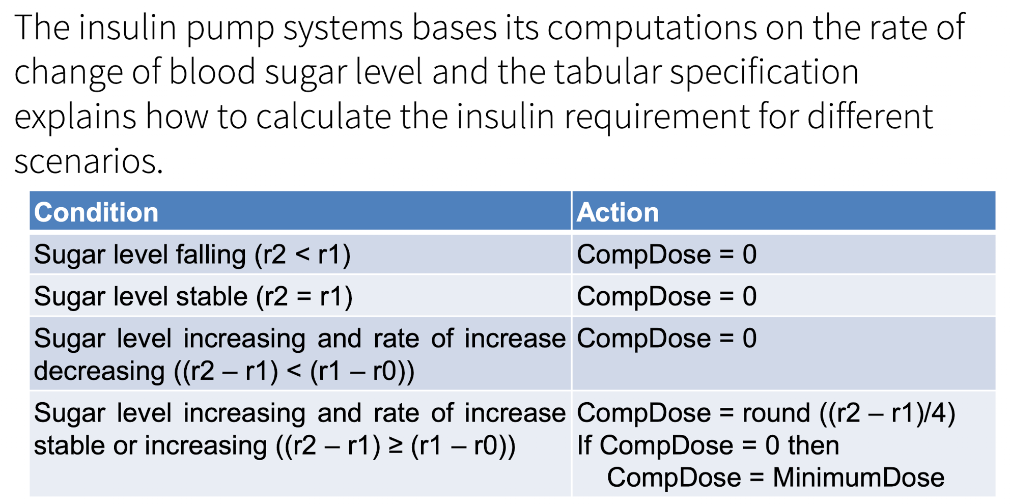
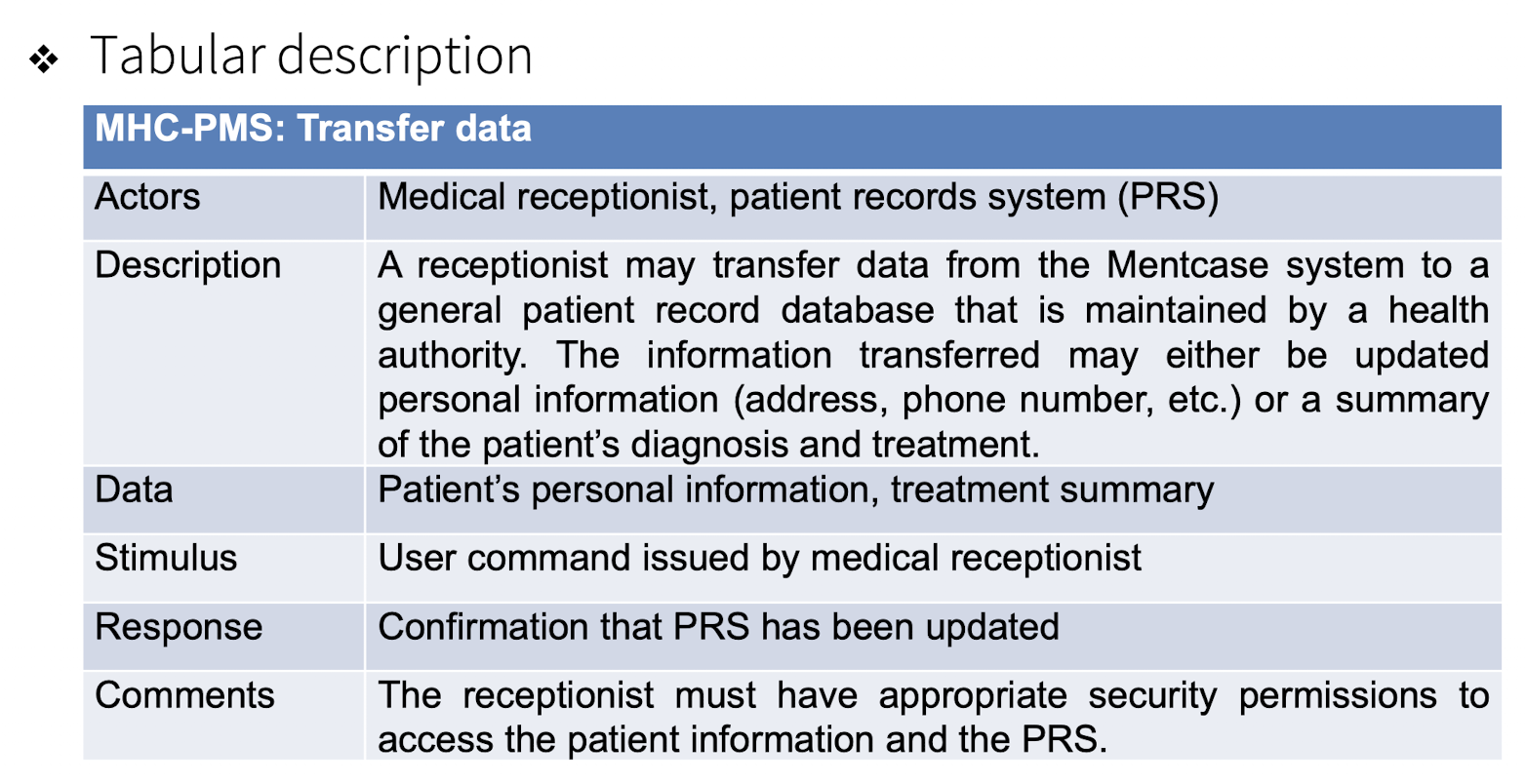
4.2.2.3 Tabular Specification
Use tables to add extra information to NL;
When encounter some conditions;
To define a number of possible alternative courses of action.
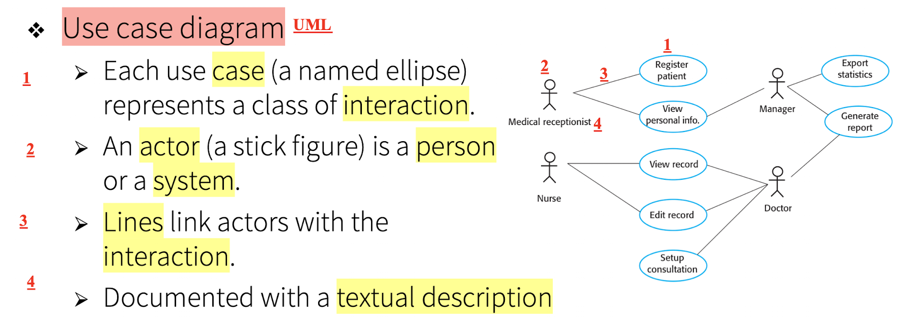
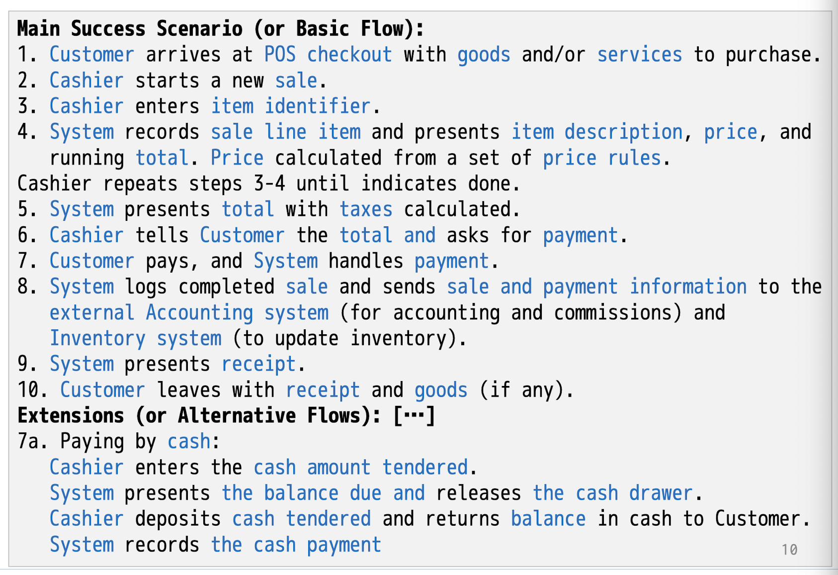
4.2.2.4 Use Cases
Describing interactions between users and a system using a graphical model and structured text.
[Example]
UML
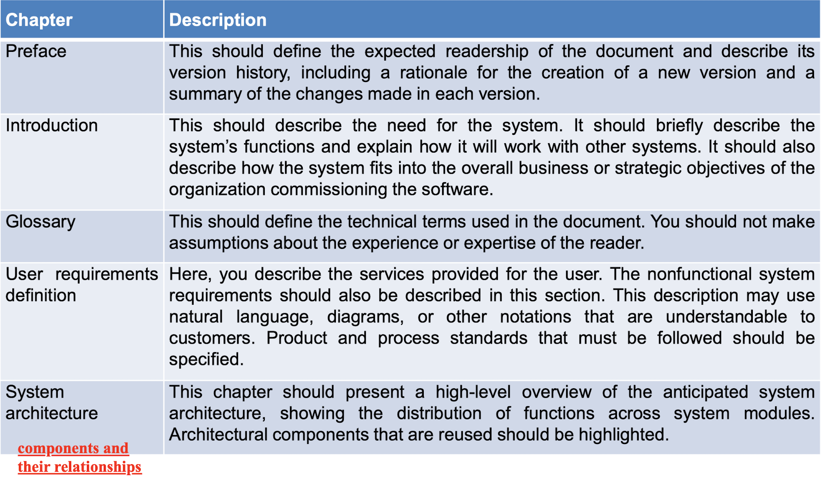
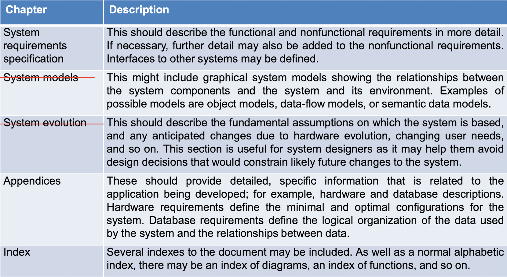
4.2.2.5 Software Requirements Specification (SRS)
The software requirements document is the official statement of what the system developers should implement;
NOT a design document. As far as possible, it should set out WHAT the system should do rather than HOW it should do it.
The Structure of A Requirements Specification:
4.2.3 Requirement Validation
Process of checking that requirements define the system that the customer really wants.
Types of checks:
- Validity checks:
- Do the requirements reflect the real needs of system users?
- Consistency checks:
- Are there any requirements conflicts?
- Completeness checks:
- Are all functions required by the customer included?
- Realism checks:
- Can the requirements be implemented, given the available budget and technology?
- Verifiability checks:
- Can the requirements be verified?
Techniques:
- Requirements reviews:
- Systematically and manually analyze the requirements;
- Be held regularly;
- Involve both client and contractor staff;
- Formal (with completed documents) or informal.
- Prototyping:
- Using an executable model of the system to check requirements;
- Get feedback form stakeholders.
- Test-case generation:
- Developing tests for requirements to check verifiability.
4.3 Requirement Change
- Problems that CANNOT be completely define, reasons:
- Have errors and omissions in the first requirement;
- Business and technical environment is changing;
- Diverse stakeholder community, which may change, and their requirements may change as well;
4.3.1 Requirements Management
- The process of managing changing requirements
during the requirements engineering process and system development; - Keep track and maintain links between relationship;
To do:
- Requirements identification
- give each requirement an ID;
- A change management process;
- minor or important?
- Traceability policies;
- Tool support.
Stages:
- Problem analysis and change specification
- Change analysis and costing
- the importance of the change;
- Change implementation (including revising the SRS)
5 System Modelling
Documenting a model that describes the real world
- The process of developing abstract models of a system
- Each model presenting a different view or perspective of that system.
In different forms:
- Graphical models: diagram - UML;
- Formal models: Mathematical; sets, functions,…
- Natural language…
Model on:
- Existing systems: clarify, discussing its strengths and weaknesses.
- System to be developed: requirements, design proposals,…
Abstraction & Representation
- Abstraction:
- Focus on the important aspects of the system, without the irrelevant details, leave out the details;
- Model is an abstraction of the system;
- Not an alternative representation;
- For a English book:
- the representation is the Chinese version;
- the slide is the abstraction of the book;
- For a English book:
- Focus on the important aspects of the system, without the irrelevant details, leave out the details;
- Representation:
- Each model represents a system from a particular perspective;
- External perspective: context or environment of the system;
- Interaction perspective: Interactions between systems and external agent between system components;
- At least two different parties, entities;
- Structural perspective: components, organizations, data structures;
- Behavioral perspective: dynamic behavior, responds;
- Only one party, entity, itself;
- Each model represents a system from a particular perspective;
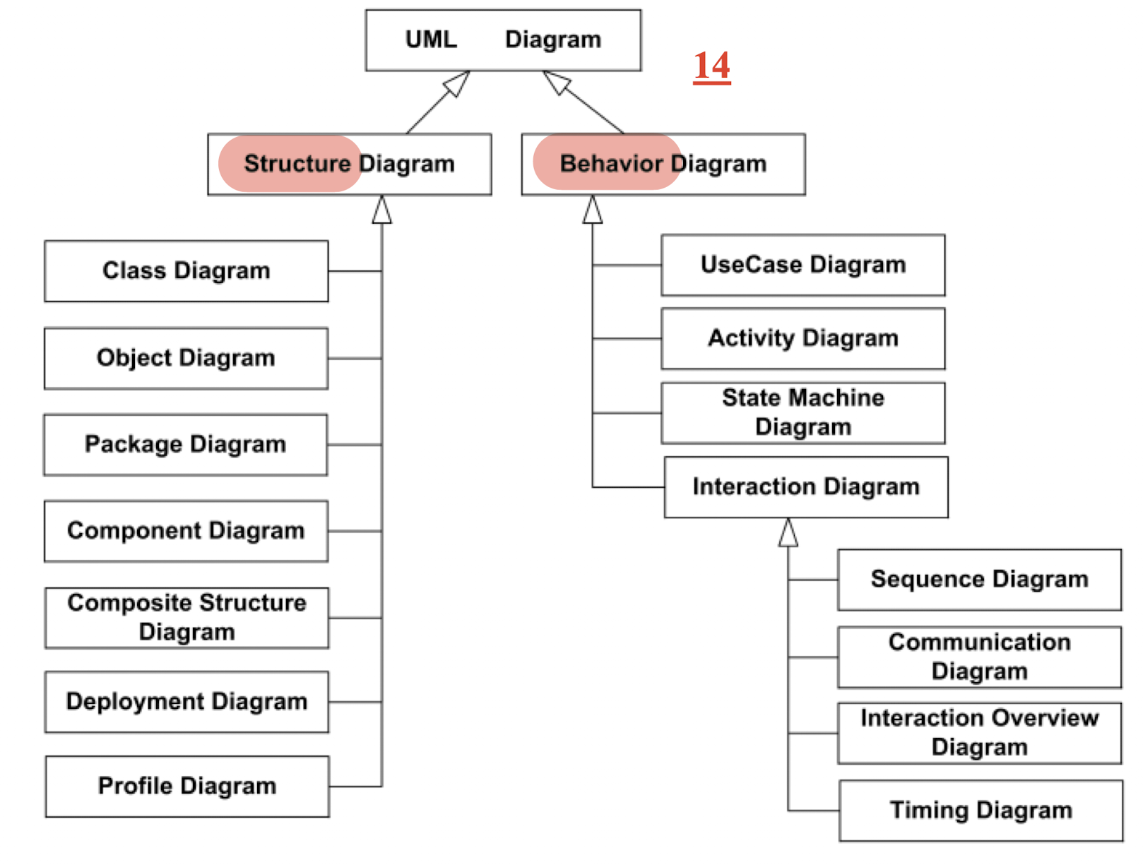
Unified Modeling Language (UML)
- May be incomplete;
- Notations may be informal;
- May for documenting only
- Should be correct;
- A detailed description can be generated through by the UML;
UML:
- General purpose modeling language (for [OO software] systems)
- A standardized language for specifying, visualizing, constructing, and documenting (software) systems.
- Specification: the language is supposed to be simple enough to be understood by the clients;
- Visualization: models can be represented graphically;
- Construction: the language is supposed to be precise enough to make code generation possible;
- Documentation: the language is supposed to be widespread enough to make your models understandable to other developers
Including different type of diagrams:
- Activity diagrams:
- which show the activities involved in a process or in the data processing.
- Use case diagrams:
- which show the interactions between a system and its environment.
- Sequence diagrams:
- which show interactions between actors and the system and between system components.
- Class diagrams:
- which show the object classes in the system and the associations between these classes.
- State diagrams:
- which show how the system reacts to internal and external events.
5.1 Context Models
What lies outside the system, people involved
Illustrate the operational context of a system - they show what lies outside the system boundaries.
System boundaries;
- Inside and what is outside the system.
- may be a political judgment;
- Example: Req depends on a system managed by a PM, who is difficult to deal with, so we have to choose another system;
Have some interaction and systems, but NO details about how to do:
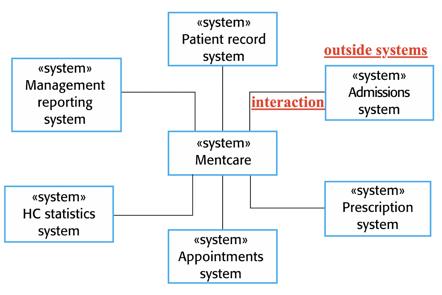
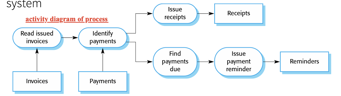
5.1.1 Process Perspective
- A type of the context;
- Context models simply show the other systems in the environment, but NOT the types of relationships between, no details;
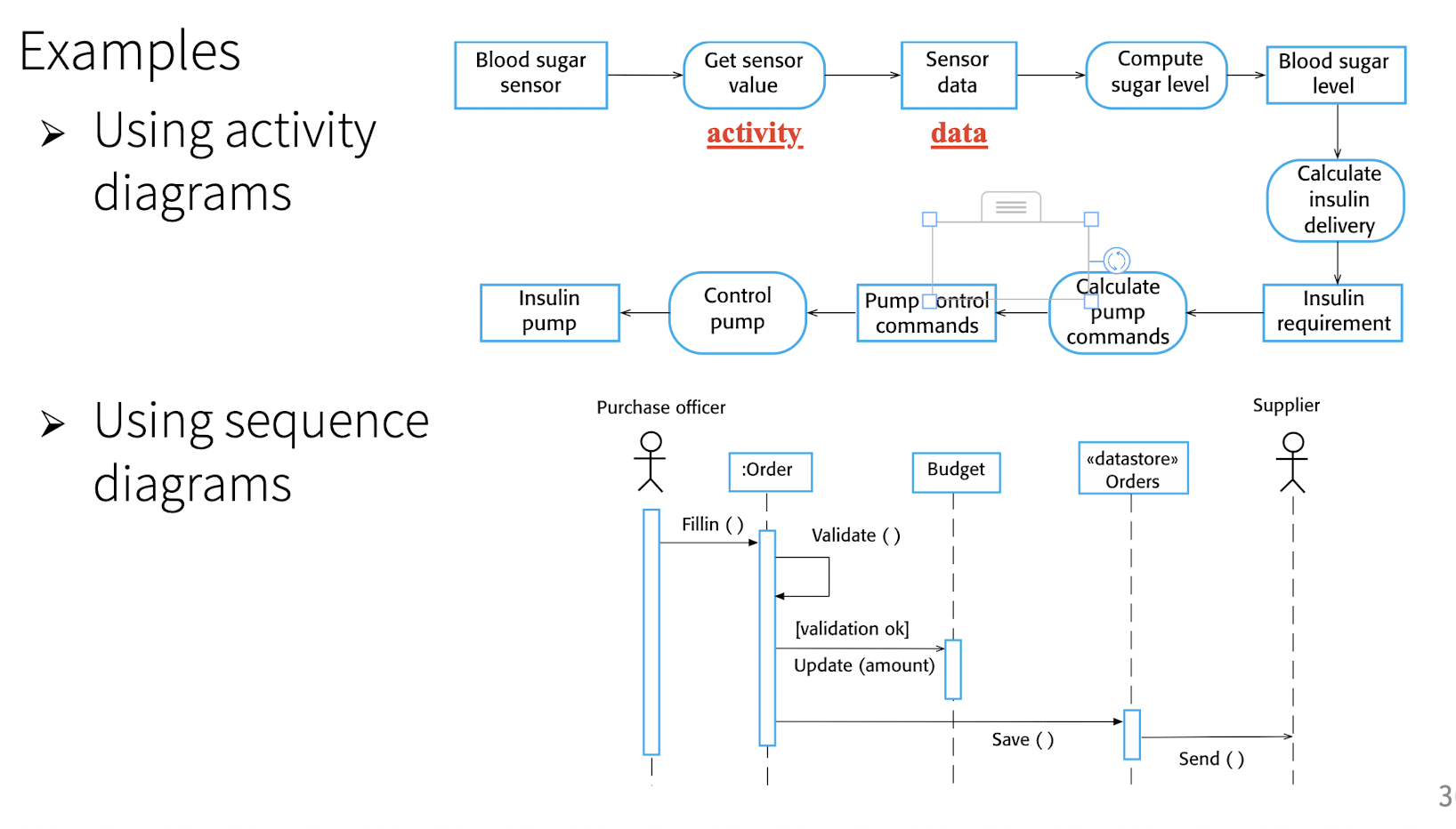
UML activity diagrams:
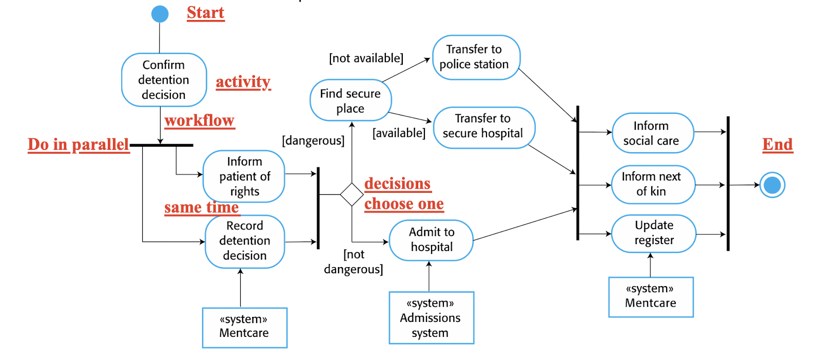
5.2 Interaction Models
Interactions
between systems and external agent;
between system components;
- User interaction:
- Identify user requirements;
- Component interaction:
- Proposed system structure;
- System-to-system interaction:
- Arise communication problems
Approaches:
- Case diagrams:
- interactions between systems and external agents
- Sequence diagrams:
- between system components
5.2.1 Use Case Modelling
Case diagram:
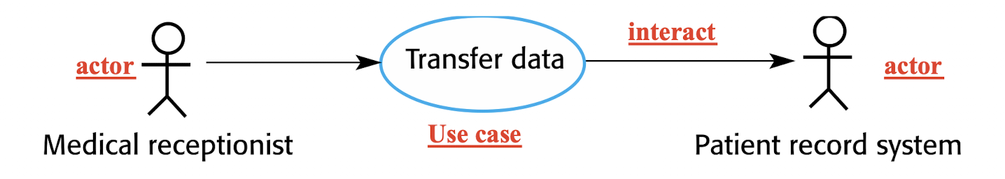
- Ellipse: use case, task;
- Stick figure: actor, person, use;
Not so many details,may be associated with simple textual description, a structured description in a table, or a sequence diagram
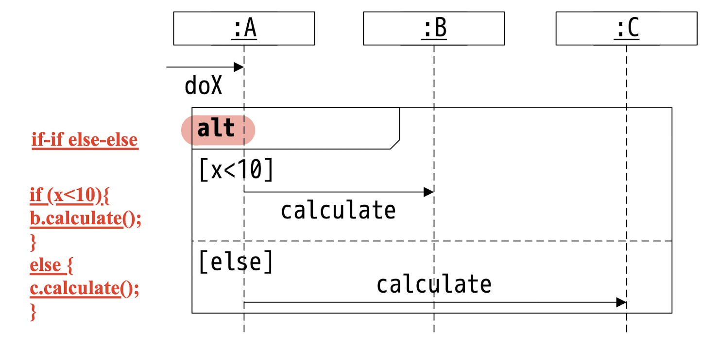
5.2.2 Sequence Modelling
- Interactions between the actors and the objects within a system and those between the objects themselves.
- Shows the sequence of interactions that take place during a particular use case or use case instance.
Sequence diagram:
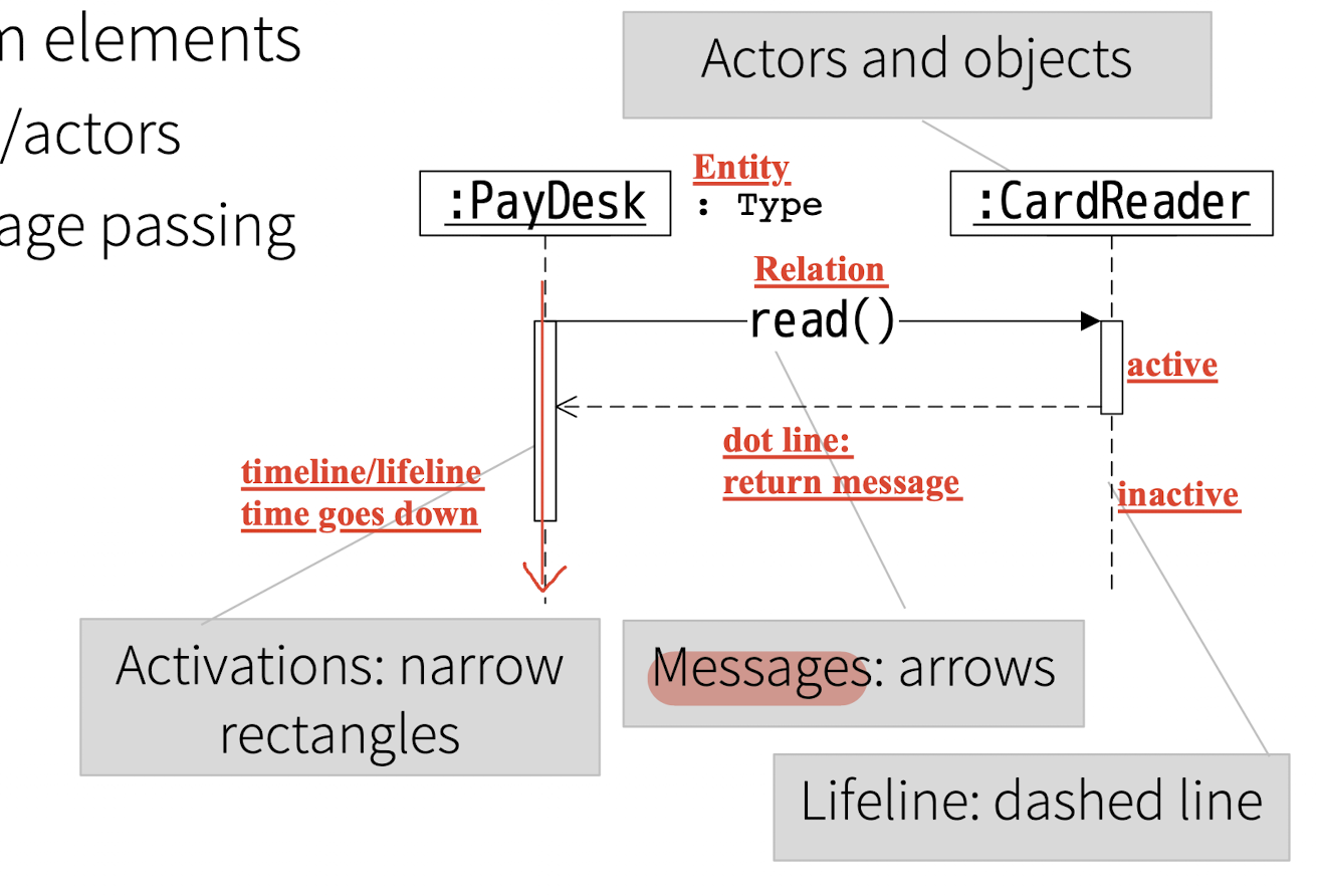
1 | |
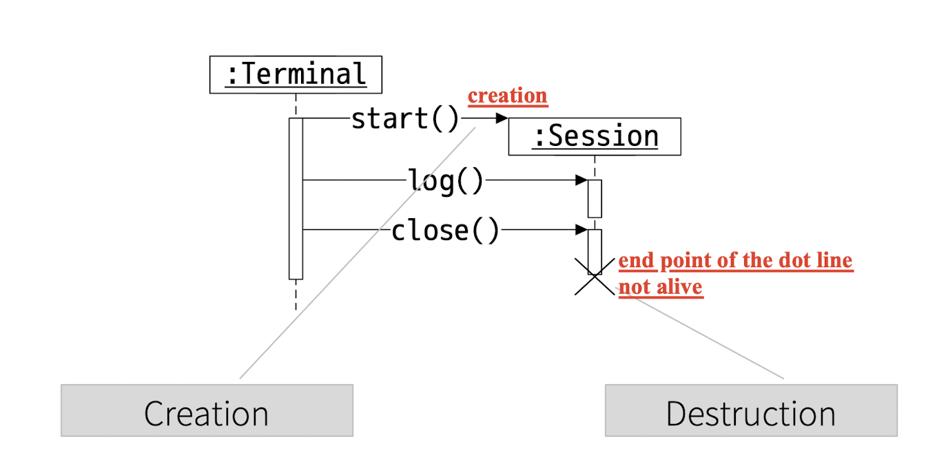
Creation and Destruction:
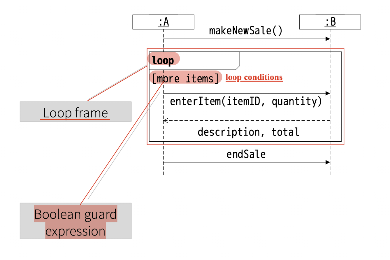
Loop:
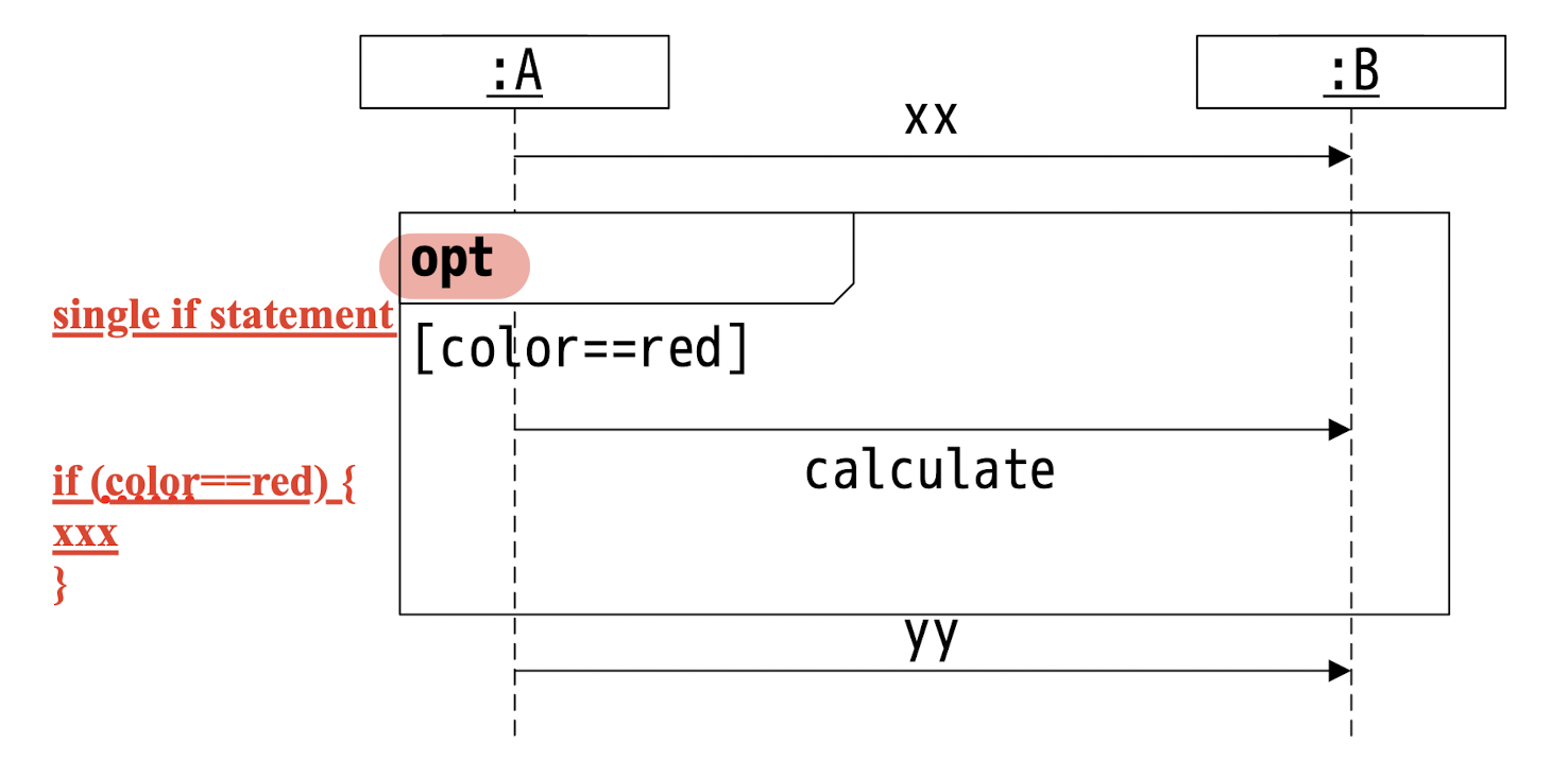
Single if:
if-if else-else:
5.3 Structural Models
System in terms of the components
Class, Objects
- The organization of a system in terms of the components
- Used when discussing and designing the system architecture
Static models: Class;
Dynamic models: Object;
Static models: Class Diagram;
- Classes and associations, the model form the real world;
- Can be used in:
- Early phase:
- Identifying classes and their relations in the problem domain(NO details);
- Implementation phase:
- high level of detail;
- Early phase:
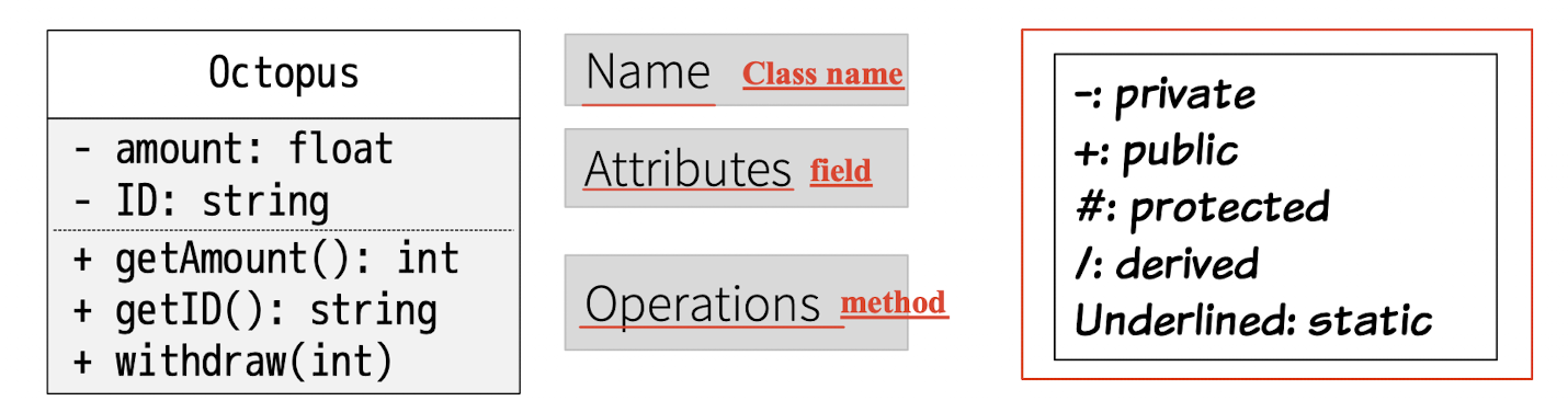
5.3.1 Class Diagram
Class name, field, method;
- Only the class name is mandatory;
- Field has type;
- Method has signature;
5.3.1.1 Relationship
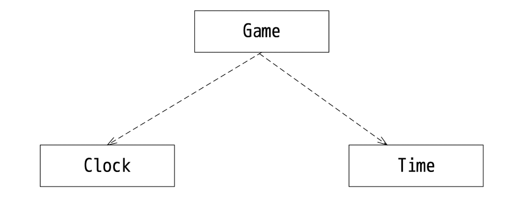
1. Dependency Relationship:
- Class-level
- Semantic connection
- A change to class
Amay cause a change to classB; - Dash line with arrow
1 | |
2. Instance-level Relationship:
For each object/instance
- 2.1 Associations:
- Give a name to de dependency
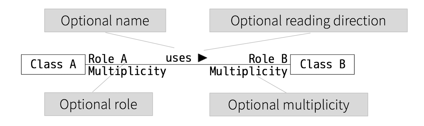
- Association Multiplicity
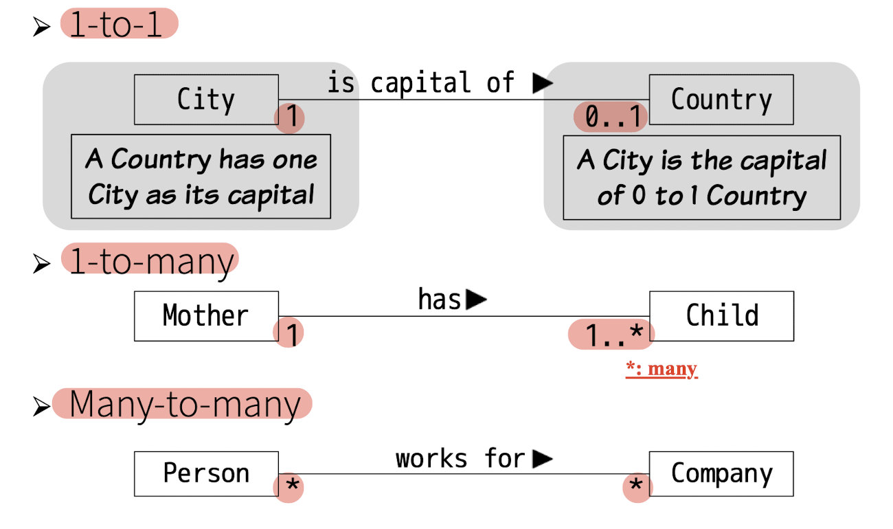
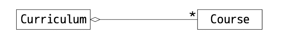
- 2.2 Aggregation:
- Special case of association;
- Has-A relationship;
- “part-of” multiple objects, one can be part(shared) of many;
- Delete Curriculum, course still exists;
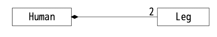
- 2.3 Composition:
- strong aggregation;
- “part-of” only single object, one can and only can be part(not shared) of one;
- Exists only together with the aggregate
- Delete a Human, Leg must gone
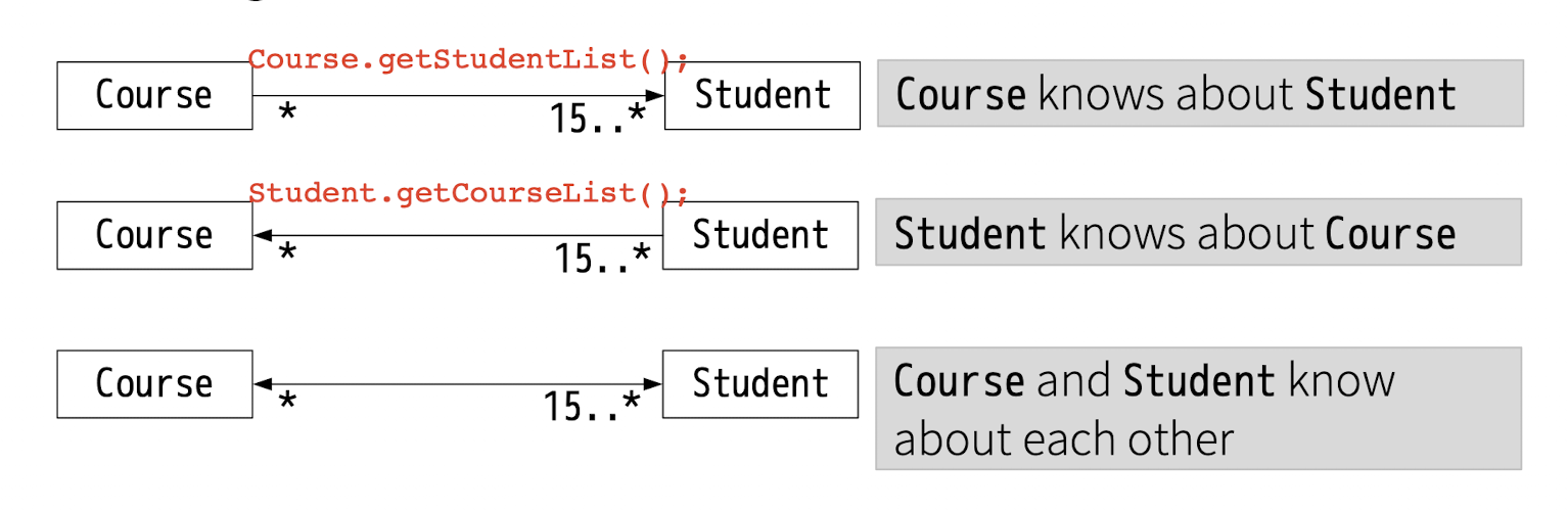
- Navigability of Association
- whether objects can be accessed through this association
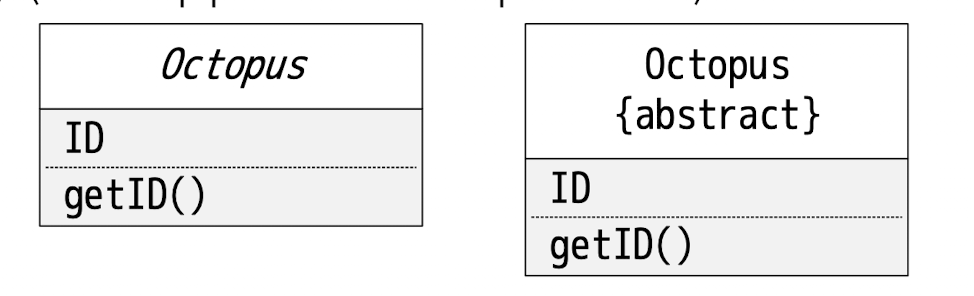
- Abstract and Interface Classes
{abstract}

<<interface>>
- Implemented by classes
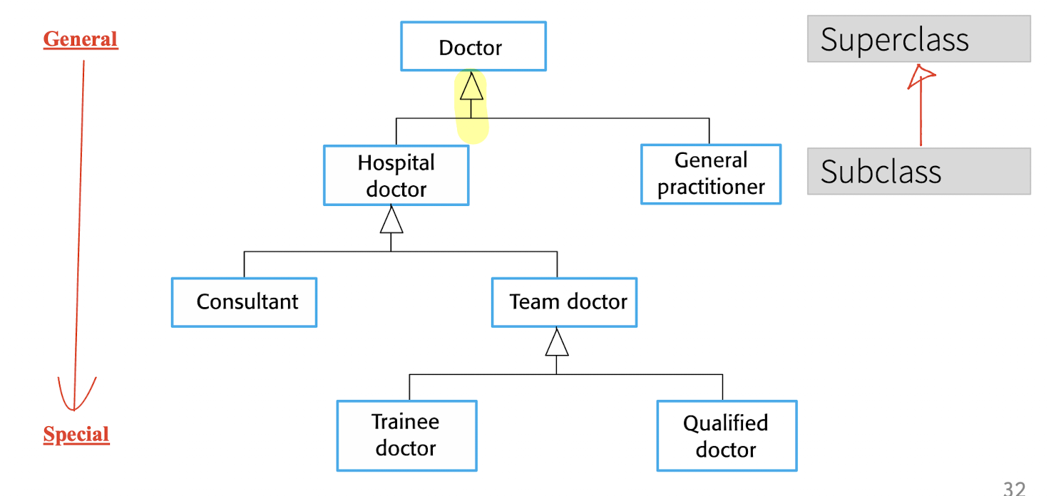
Class-level Relationship:
Is-Arelationship;- Inheritance;
- More general(superclass) and more detailed(subclass);
- Generalization simplifies the model by eliminating redundancy;
5.4 Behavioral Models
A system responds to a stimulus from its environment.
- the dynamic behavior of a system as it is executing;
- Sequence/Use case diagram;
- system responds to a stimulus from its environment.
- stimulus:
- Data
- Event
- stimulus:
5.4.1 Data-Driven Modeling
- Sequence of actions in processing input data and generating an associated output.
- Using:
- Activity Diagrams
- Sequence Diagram
- Using:
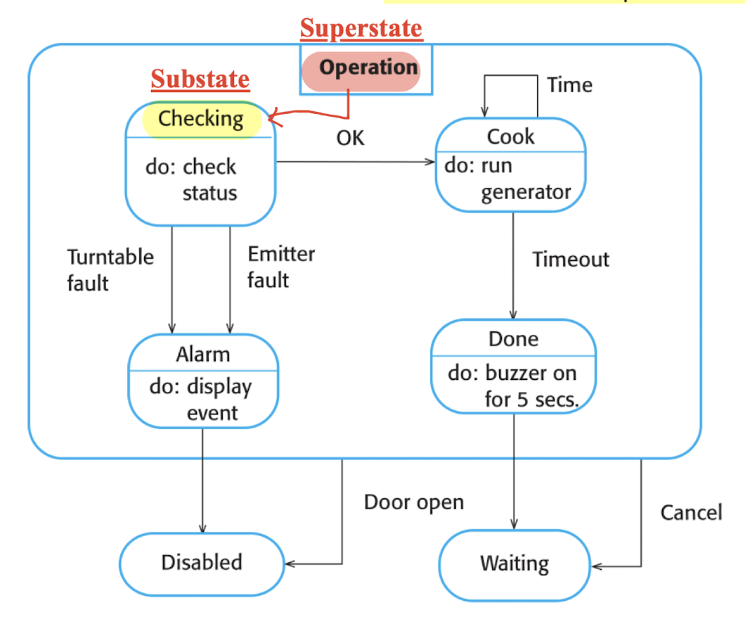
5.4.2 Event-Driven Modeling
- System responds to external and internal events.
- State Diagram:
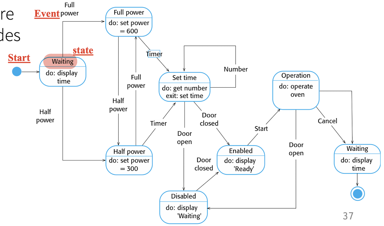
Superstate:
- Modelling states at different levels
- Group several state into a higher state;
5.5 Model-Driven Engineering (MDE)
Models rather than programs;
Abstractions;
Generate model to be ran in different platforms;
6 Architectural Design
How a software system should be organized and designing the overall structure of the system.
- Between design and requirement
- main structural components in a system and the relationships between them.
- Output: architectural model
With agile:
- Focus on designing an overall systems architecture
With plan-driven:
- Overlap between the two processes of requirements engineering and architectural design.
Abstraction:
- Architecture in the small
- Inside an individual program, without the surrounding context;
- Individual systems;
- Architecture in the large
- enterprise systems that include other systems,
- Systems of systems;
Advantages of *Explicit* Architecture
- Stakeholder communication:
- high-level presentation;
- Be understandable by non-technical people;
- Discussed by a range of different stakeholders;
- System analysis:
- Whether or not the system can meet critical requirements;
- Large-scale reuse:
- be reusable across a range of systems (in large)/ reuse of code (in small);
- Product-line developed.
- Since a lot of product can be reused;
- For efficient development;
- Share same application families/domain;
- e.g. MS Office, different editions share same applications;
Representations
- At the end of design; then to represent;
- Using simple block diagrams.
- Boxes: component decomposition
- Arrows: data and control flow
- Two opinions:
- Lack semantics, less details;
- Useful for communication with stakeholders and for project planning.
Usages:
- For discussion about the system design
- For documenting an architecture that has been designed
6.1 Architectural Design Decisions
The solution to the architecture choose;
- Reuse: template of generic application architecture
- Similar application from the same domain, as the start point/template;
- How distribute across hardware core/processors? (optional);
- What patterns should be used?
- Summary good practice from the past
- Best for delivering the non-functional?
- How should the architecture of the system be documented?
Architecture on Non-Functional Requirements:
- Performance:
- Localize critical operations, minimize communications:
- In local, not remote;
- Using large, NOT small components/fine-grain;
- Localize critical operations, minimize communications:
- Security:
- Working under attack;
- layered architecture with critical assets in the inner layers.
- Use top layer to protect the inner layer;
- Safety:
- Will not cause harm to the user and others;
- Localize safety-critical features in a small number of sub-systems;
- Perform several checking for each small sub-system rather than one big system;
- Availability:
- Include redundant components and mechanisms for fault tolerance.
- e.g. Multiple servers for a web application; one down, other can still provide service;
- Include redundant components and mechanisms for fault tolerance.
- Maintainability:
- Use fine-grain, self-contained components that may easily be changed.
- Easy to replace problem components;
- Easy to extend;
- Use fine-grain, self-contained components that may easily be changed.
May be some conflicts between some of these choices:
- e.g. Performance and Maintainability;
- usage of fine-grain;
6.2 Architectural Views
Different view on a architecture design;
- Each architectural model only shows one view;
- Need to present multiple views of a software architecture.
- how a system is decomposed into modules: block diagram;
- run-time processes interact: activity diagram;
6.2.1 View Models of Software Architecture
4 + 1 model:
- FOUR fundamental architectural views that are linked through
- ONE common use cases or scenarios;
FOUR views:
- A logical view, which shows the key abstractions in the system as objects or object classes.
- A process view, which shows how, at run-time, the system is composed of interacting processes.
- I/O
- A development view, which shows how the software is decomposed for development.
- A physical view, which shows the system hardware and how software components are distributed across the processors in the system.
- Deplored
(conceptual view may be added: block diagram)
6.3 Architectural Patterns
Patterns:
- A way of presenting, sharing, and reusing knowledge about software systems.
A stylized description of good design practice, which has been tried and tested in different systems and environments.
Architectural patterns:
- The Model-View-Controller (MVC) pattern
- The Client-Server pattern
- The Pipe and Filter pattern
- The Layered pattern
- The Repository pattern
6.3.1 Model-View-Controller (MVC) Pattern
Model:
- Manages the system data and associated operations on that data.
- Model the real world;
- Should happen in the real world;
View:
- Defines and manages how the data is presented to the user.
- For a java file: editing view, read-only view, class view, etc…
Controller:
- Manages user interaction (e.g., key presses, mouse clicks, etc.) and passes these interactions to the View and the Model.
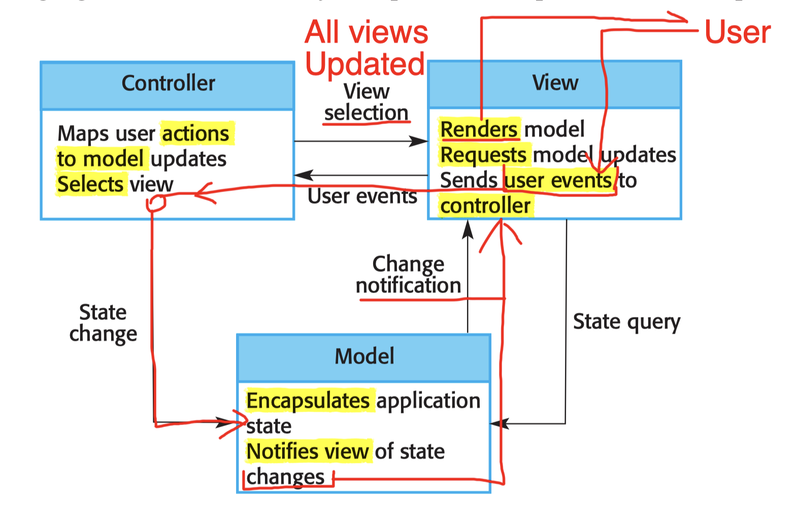
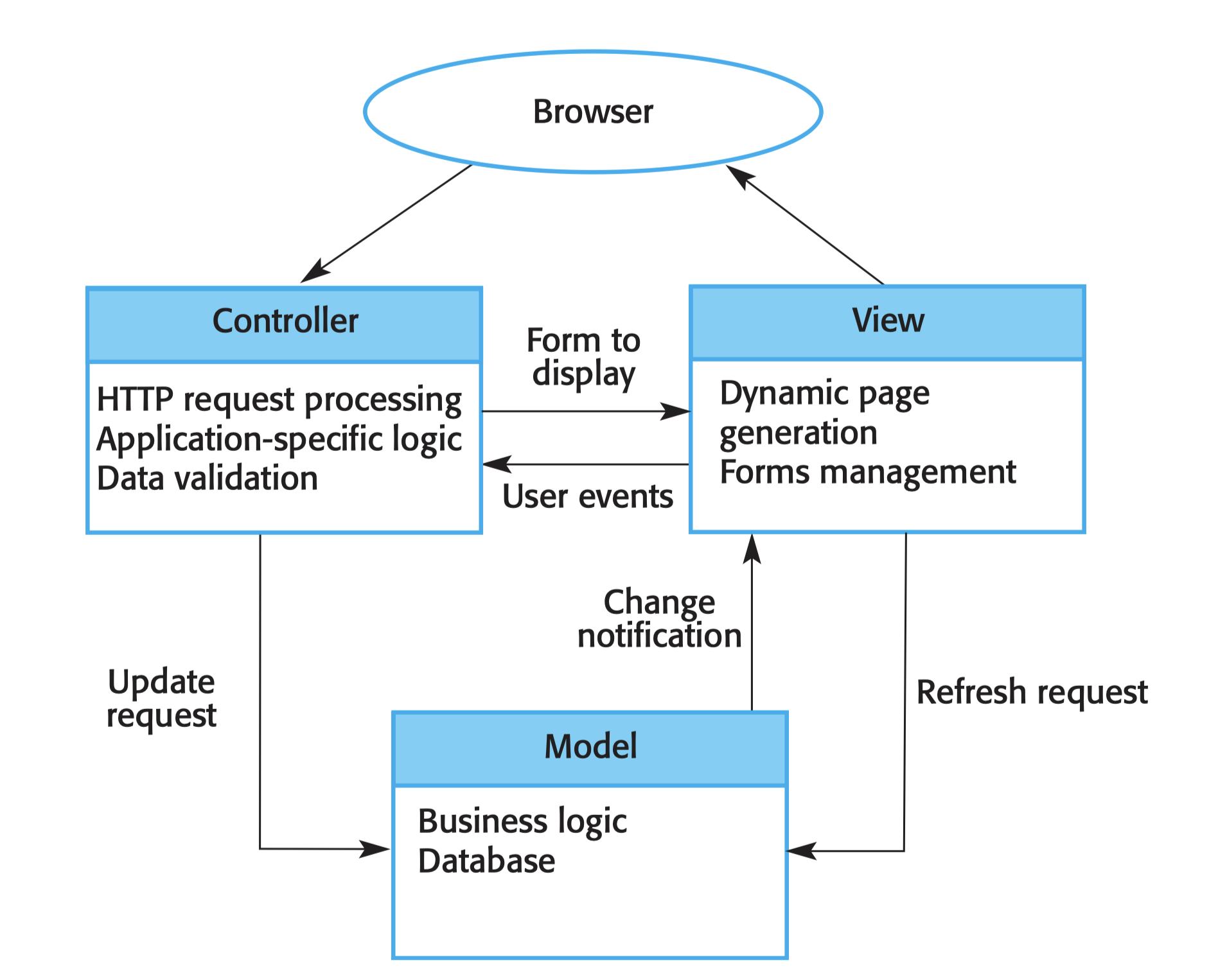
Usage:
- Multiple ways to view and interact with data
- editing view, read-only view, class view, etc
- Changes in one view should be updated in other views;
- The future requirements for interaction and presentation of data are unknown.
- e.g., Course project: from CLI to GUI, no need to change the Model.
- Views can be changed independently to the Model;
Advantage:
- Data to change independently of its representation and vice versa;
- Weak coupling;
- Presentation of the same data in Advantages different ways
Disadvantage:
- Involve additional code and code complexity;
- Especially when the data model and interactions are simple.
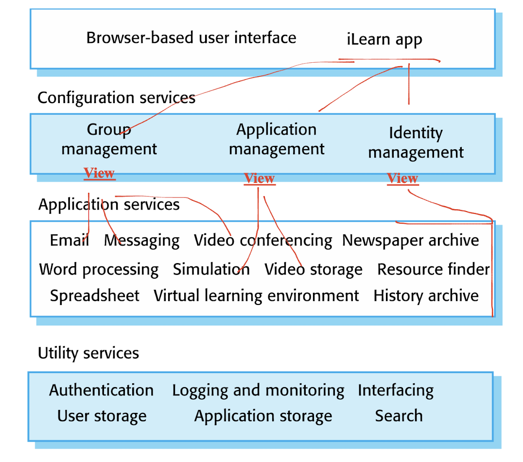
6.3.2 Layered Pattern
Organized into separate layers, and each layer ONLY relies on the facilities and services offered by the layer immediately beneath it.
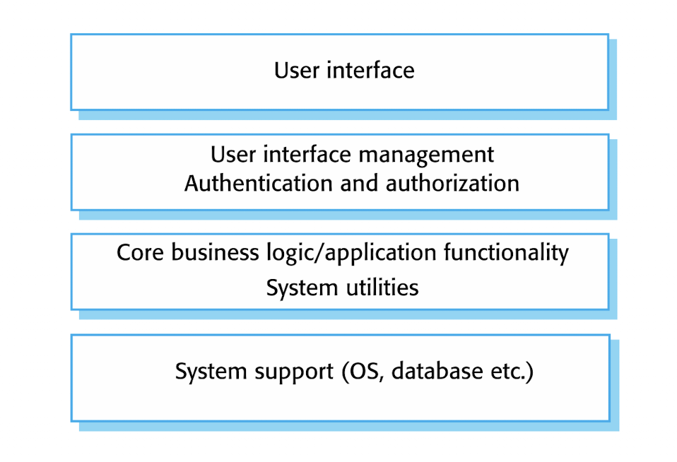
Benefit:
- Supports the incremental development;
- Layer interface changes, ONLY the adjacent layer is affected;
- Allows replacement of entire layers;
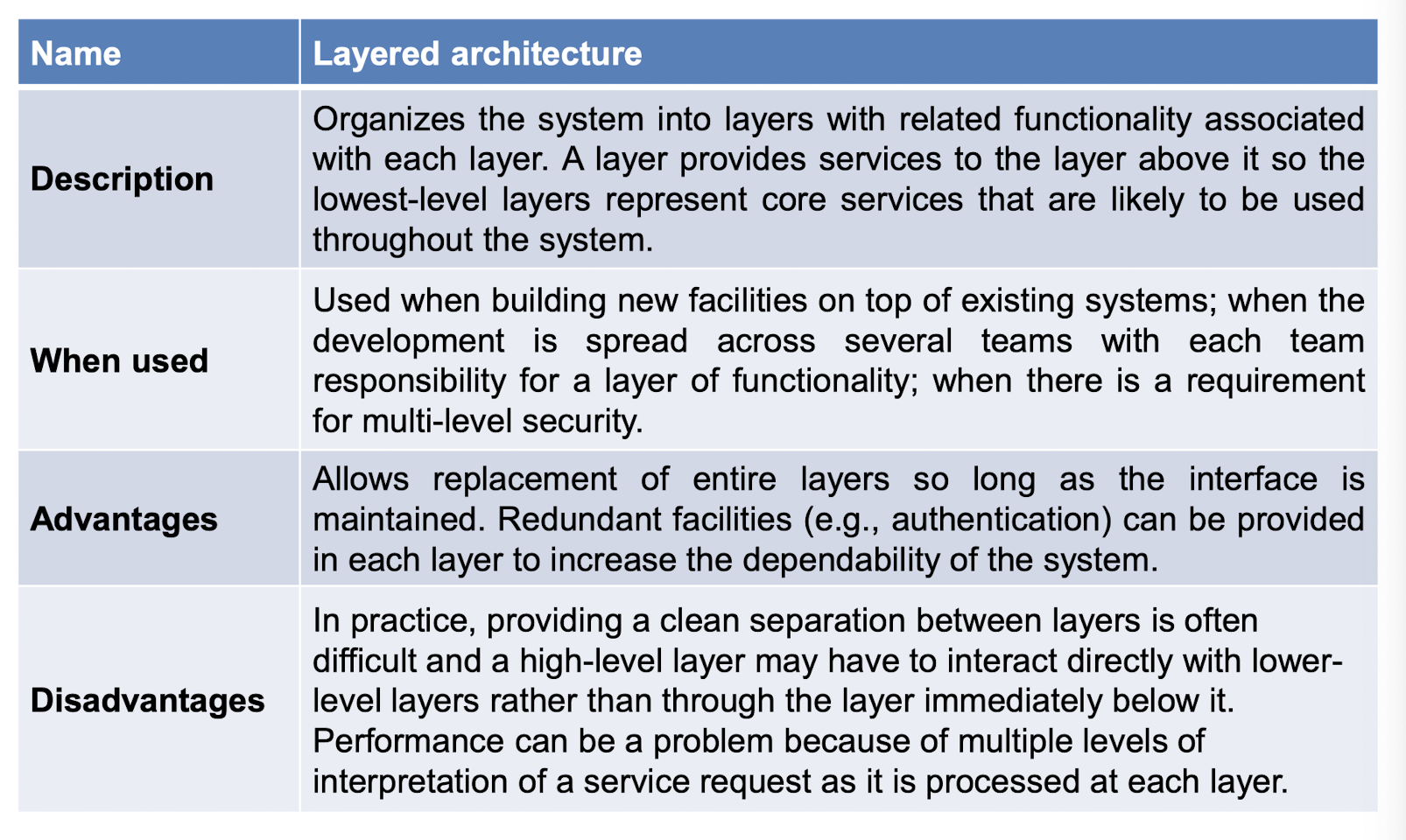
Disadvantage:
- Clean separation between layers is often difficult
- High-level layer may have to interact directly with lower-level layers rather than through the layer immediately below it.
- e.g., from 1 to 3 directly, not access 2; 2 provide a special gate;
- the performance will be low;
6.3.3 Repository Pattern
Exchange of data in:
- Shared data is held in a central database. High efficiency;
- Sub-system maintains its own database(copy of) and passes data explicitly to other sub-systems. Low efficiency;
- process the data, but NOT present to users, no view;
- But in MVC, the V will take the presentation to the user.
Benefit:
- Components can be independent;
Disadvantage:
- Repository is a single point of failure
- Repo done, whole done;
- Distributing may be difficult;
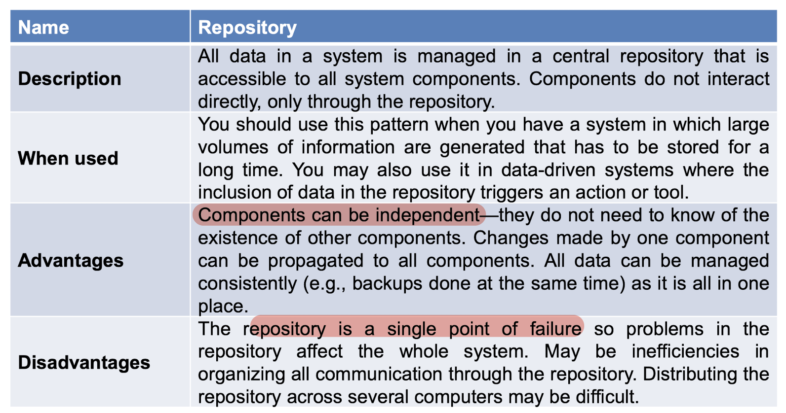
Repository model: A repository is passive, the components to control with the data in repository;
Blackboard model: A blackboard notifies(actively) components when particular data become available;
- Updates in the blackboard will notifies other components;
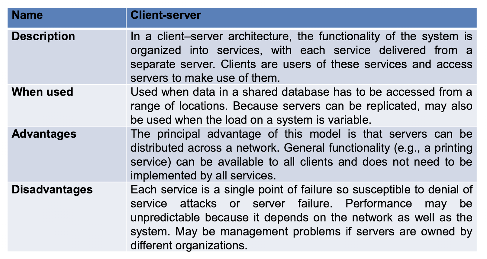
6.3.4 Client–Server Pattern
For distributed system model.
Stand-alone servers:
- provide specific services such as printing, data management, etc.
Clients:- call on these services they want to;
Advantages:
- Servers can be distributed across a network;
- Servers can also be client to access other servers;
Disadvantage:
- Performance may be unpredictable because it depends on the network;
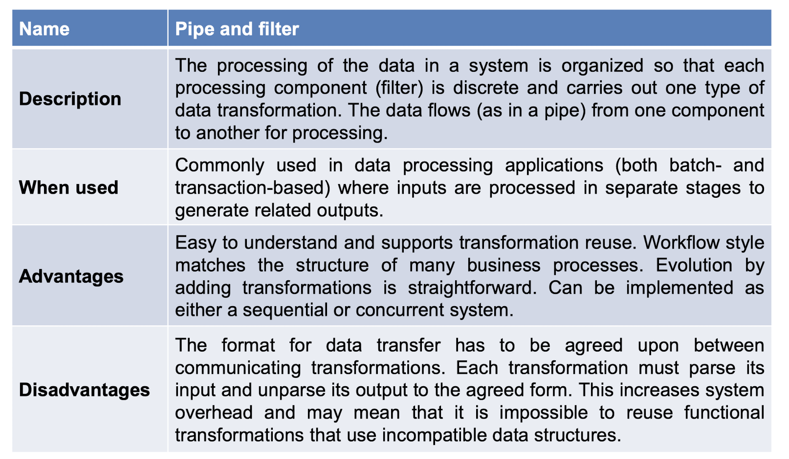
6.3.5 Pipe and Filter Pattern
The runtime organization of a system where functional transformations process inputs and produce outputs
- pipes: link processes using “pipes.”;
- filter: transformation “filters out” the data it can process from its input data stream.
Usage:
- Best suited to batch processing systems and
- embedded systems
- where there is limited user interaction, but not really suitable for interactive systems.
Advantages:
- understand and supports transformation reuse;
- matches the structure of many business processes;
Disadvantage:
- data transfer has to be agreed;
- Each transformation must parse its input and unparse its output to the agreed form;
6.4 Application Architecture
- An architecture that encapsulates the principal characteristics of a class of systems;
- Be configured and adapted to create a system that meets specific requirements.
Usage:
- As a starting point for architectural design.
- As a design checklist.
- As a way of organizing the work of the development team.
- As a means of assessing components for reuse.
- As a vocabulary for talking about application types.
- Make communication between developer much easier, like ‘MVC’;
6.4.1 Application Types
6.4.1 Transaction processing applications
Database-centred applications;
User requests for information and update;
Like E-commerce systems and information systems
a customer request to withdraw money from a bank account using an ATM
- May be organized as a “pipe and filter” architecture
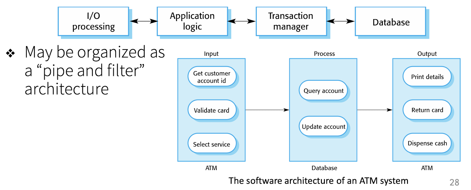
- May be organized as a “pipe and filter” architecture
Information Systems
- can be organized as a layered architecture.
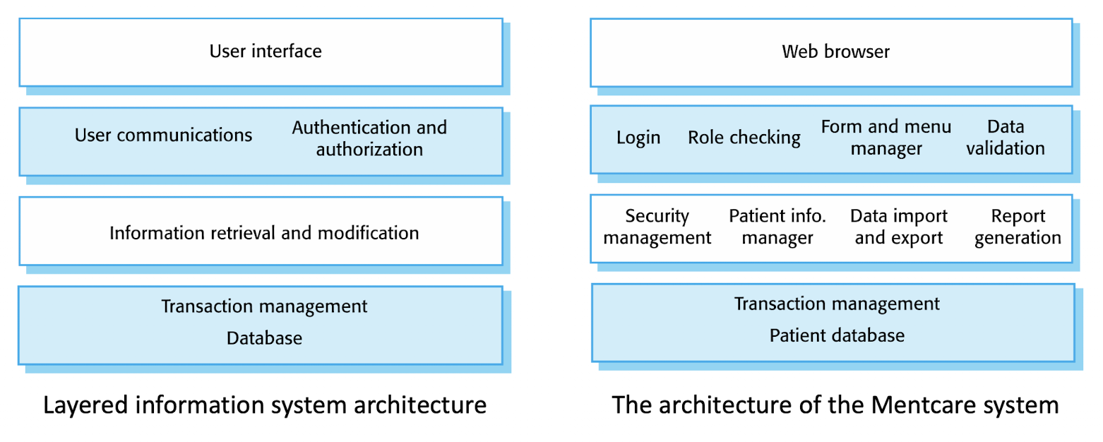
- can be organized as a layered architecture.
6.4.2 Language processing systems
7 A Brief Introduction to OOP in Java
Primitive data types: boolean, char, byte, short, int, long, float, double
Reference data types: String, Date, etc;
7.1 Class and Object
Filed (instance variable/state): the values can be stored;
Method: the operations can be performed;
Object:
- contains all the fields in the class, and takes space;
- Methods do NOT take any space in objects;
- Multiple references can point to the same object (aliasing);
Reference: only contain NULL or the address of the object;
1 | |
Call method: Sending a message to an object
Complier: Java -> C++ -> C
Constructor: special method to initialize the objects
- MUST: Same name;
- MUST: No return type, not even void;
- May have parameters, not this;
If add void:
1
2
3
4
// a regular method called Hero
void Hero() {
  // ...
}
1 | |
Method overload:
- Method signature = Method name + List of parameter types;
- Using signature to distinguish different methods, even with the same name;
7.2 Encapsulation
Information hiding.
Principle of Least Privilege
Every module must be able to access only the information and resources that are necessary for its legitimate purpose.
public(all) > protected(package+subclass) > default(package) > private(same class only)
7.3 Inheritance
IS-A relationship, reuse.
- To be part of:
- Instance variables of the superclass are PART of the objects of the subclass (Whatever public, private, protected, default);
- To inherit:
- Public variables of the superclass are inherited into the subclass, which means the subclass can access them directly by using the variable name in the superclass;
8 Object-Oriented Analysis and Design
8.1 Object-Oriented Analysis
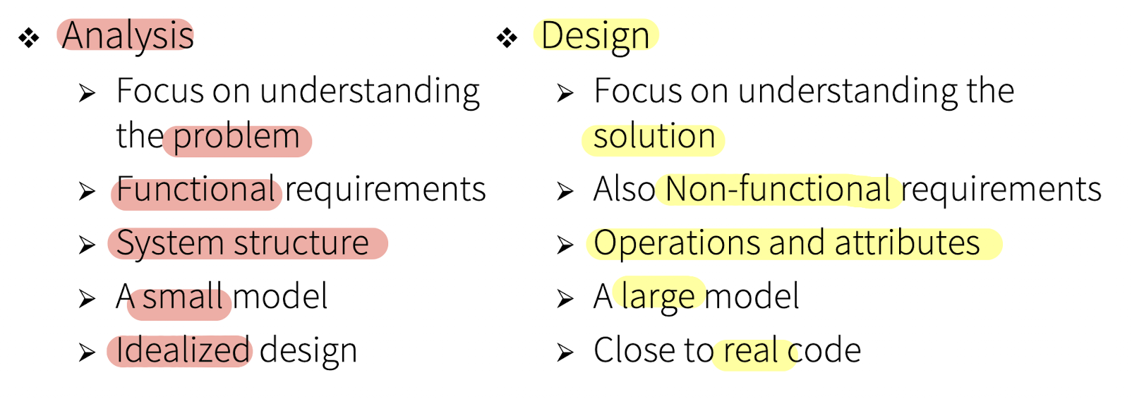
- Goal: understand the problem and to begin to develop a model of what you are trying to build (problem domain);
- Independent of implementation and technology concerns. (irrelevant to)
- Translating the functional requirements into software concepts.
- Take the non-functional requirements into consideration when design;
Two ways of analysis:
- Function-oriented analysis – concentrating on the decomposition of complex functions to simple ones.
- Object-oriented analysis – identifying objects and the relationship between objects.
8.1.1 Domain Model
Visual representation of conceptual classes in a domain of interest
- Classes, like,
Doctors,Patients,Insurance companiesin a hypothetical medical system;
- Using UML notation, like Class Diagram.
Including:
- Conceptual Classes;
- Associations between classes;
- Attributes;
Not in domain model:
- Software artifacts: windows, database;
- Responsibilities or methods.
1. Conceptual Classes:
- A real-world concept or thing, NOT an implementation class
- It is better to over-specify a domain model with lots of fine grained conceptual classes than to under-specify it.
Two ways to identify the Conceptual Classes:
- Conceptual class category
- Pre-defined categories of objects, just find, take and use; to get started; Summarize the experience of similar projects before.
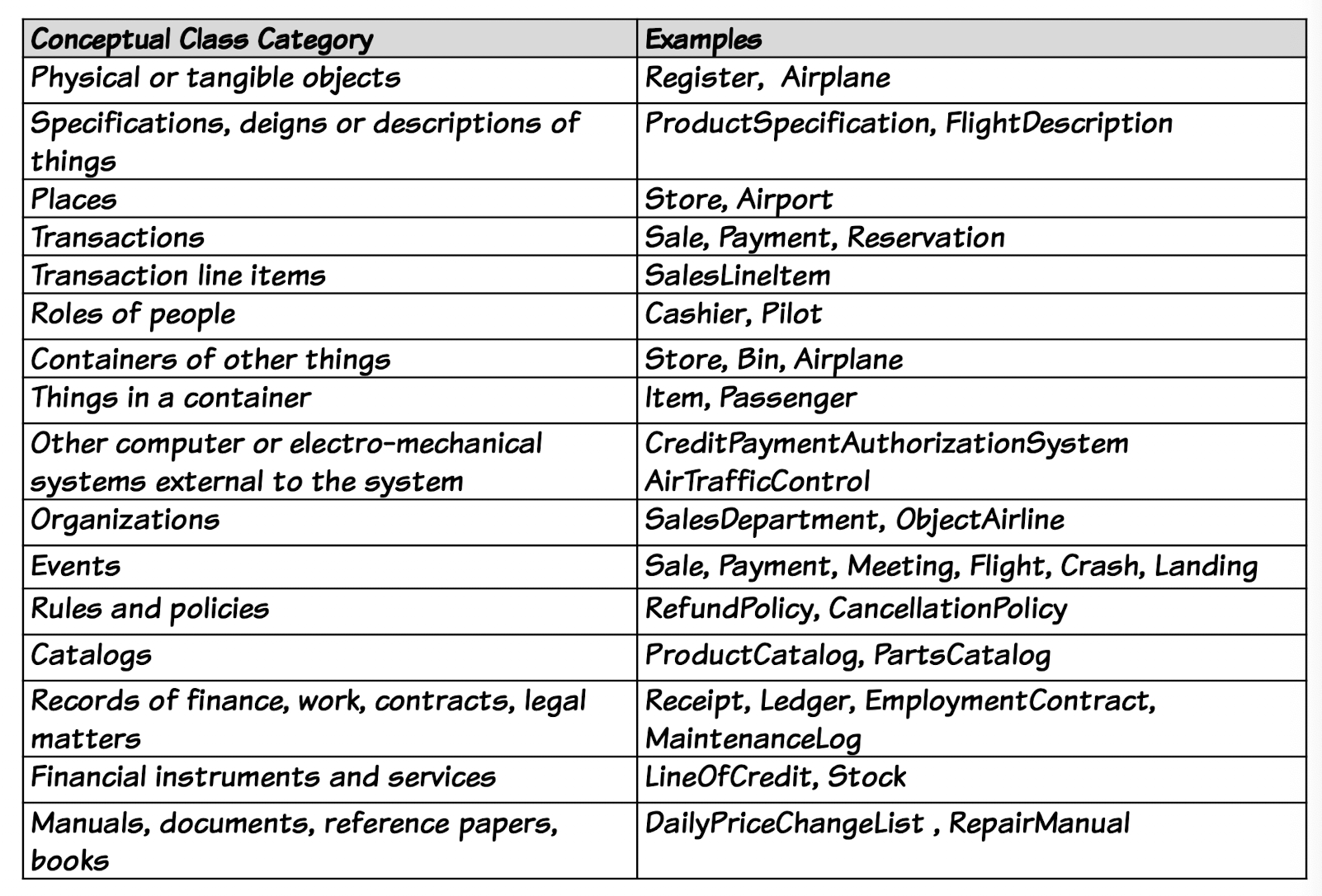
- Noun phrase identification
- To find the nouns used in the specification;
- Gather theses noun phrases;
Discard some class when:
- 1.Outside the current requirements:
Price Rule; - 2.Redundant:
System; - 3.Looks like an attribute more than a class:
Price; - 4.Not being considered in this iteration:
Receipt;like 1, think in one iteration;
No correct set of conceptual classes, diff ppl may use diff analysis.
2. Associations between classes
Relationship between types (or instances of those types)
- Name, Role, Reading direction, Multiplicity
- Aggregation vs. Composition
- Navigability, has direction
It is only the relationship is meaningful in a purely conceptual sense.
How to find the relationship:
- more important to identify conceptual classes than to
identify associations. - Too many associations tend to confuse;
- Avoid showing redundant or derivable associations.
3. Attributes
A logical data value of an object
- Mistake 1: may treat a class as an attribute;
- Like treat a
destination(Airport) as a class than as a attribute of aflight;- Good rule: If we do NOT think of some conceptual class X as a number or a piece of text in the real world, X is probably a conceptual class, NOT an attribute.
- Mistake 2: Add a kind of foreign key attribute, as is typically done in relational database designs,
8.2 Object-Oriented Design
- Goal: uses the products of analysis to produce a specification for implementing a system.
- Defining software objects(not conceptual class) and how they collaborate to fulfill the requirements.
- In details;
- Design activities, like database design and interface design
- Result:
- Specification of a logical software solution in terms of software objects,
- such as their classes, attributes, methods, and collaborations.
- Specification of a logical software solution in terms of software objects,
Two kinds of design models: dynamic and static.
Static:
- definition of packages, class names, attributes, and method signatures (but not method bodies).
- Class UML;
- Key activity: get class and sssign responsibilities to classes/objects!
- responsibilities: a doing or knowing service or a group of services provided by an element
Dynamic:
- logic and the behavior of the code or the method bodies.
- Interaction UML;
- Activity UML
8.2.1 Doing and Knowing Responsibilities
Doing responsibilities:
- Methods:
- creating an object or doing a calculation
- Initiating;
- Controlling and coordinating activities
- Methods:
Knowing responsibilities:
- Private encapsulated data;
- Related objects; (you know where to get the data)
- Things it can derive or calculate (you have the thing to be in a calculation);
8.2.2 Responsibility-Driven Design (RDD)
Software objects are like people with responsibilities who
collaborate to get work done;
- RDD is implemented by means of methods
- Either act alone or collaborate with other methods and objects.
- Assign different method to different class;
How to do RDD:
- Using Class-Responsibility-Collaborator (CRC) Cards
- One card per class,
- Having responsibilities and with which other class(es) it must collaborate in order to fulfill each responsibility.
- One card per class,
- A brief description of the class on the back of the card.
- CRC cards are useful in detecting responsibilities of objects
8.3 SOLID DESIGN PRINCIPLES
SOLID:
- Single responsibility principle
- Open/closed principle
- Liskov substitution principle
- Interface segregation principle
- Dependency inversion principle
8.3.1 Single Responsibility Principle
Each responsibility is a reason for change.
A class should have ONLY ONE reason to change.
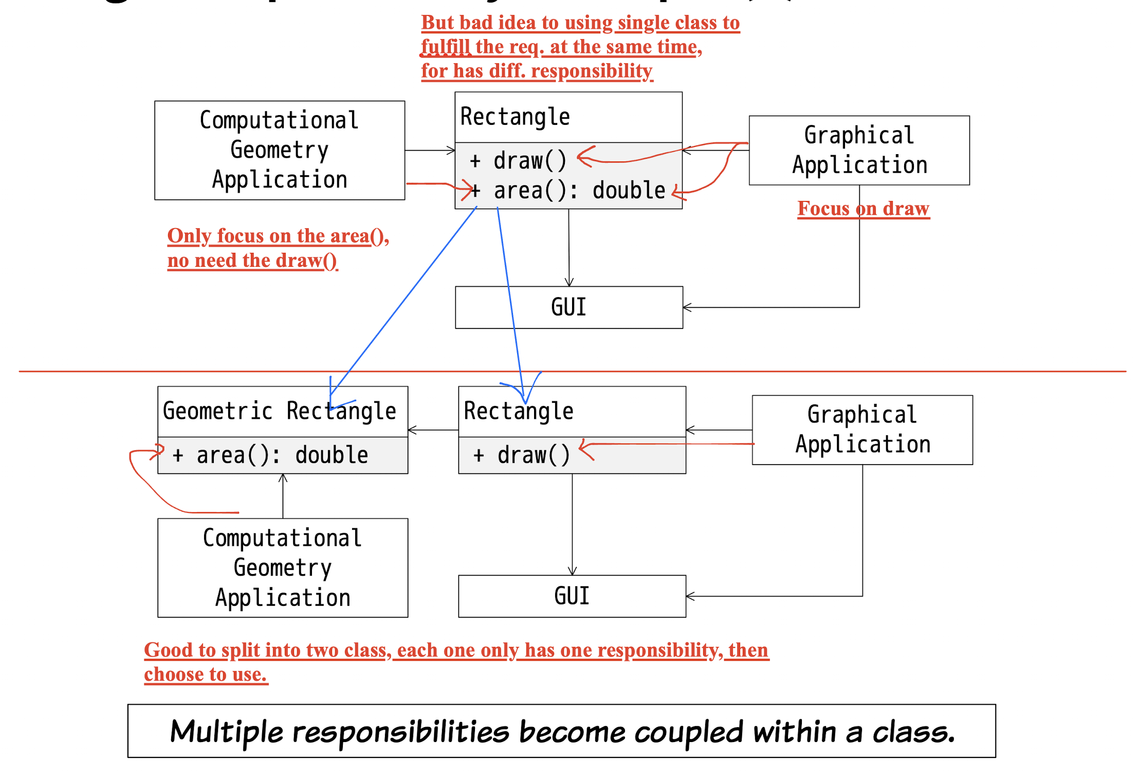
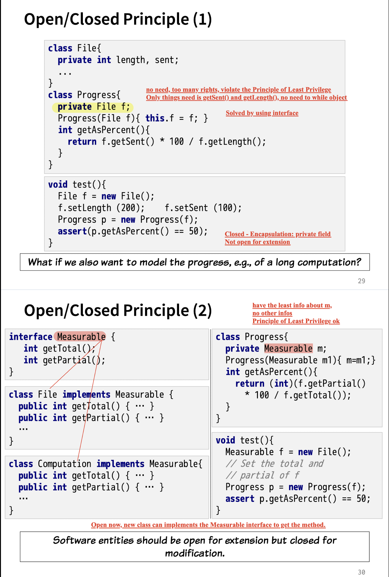
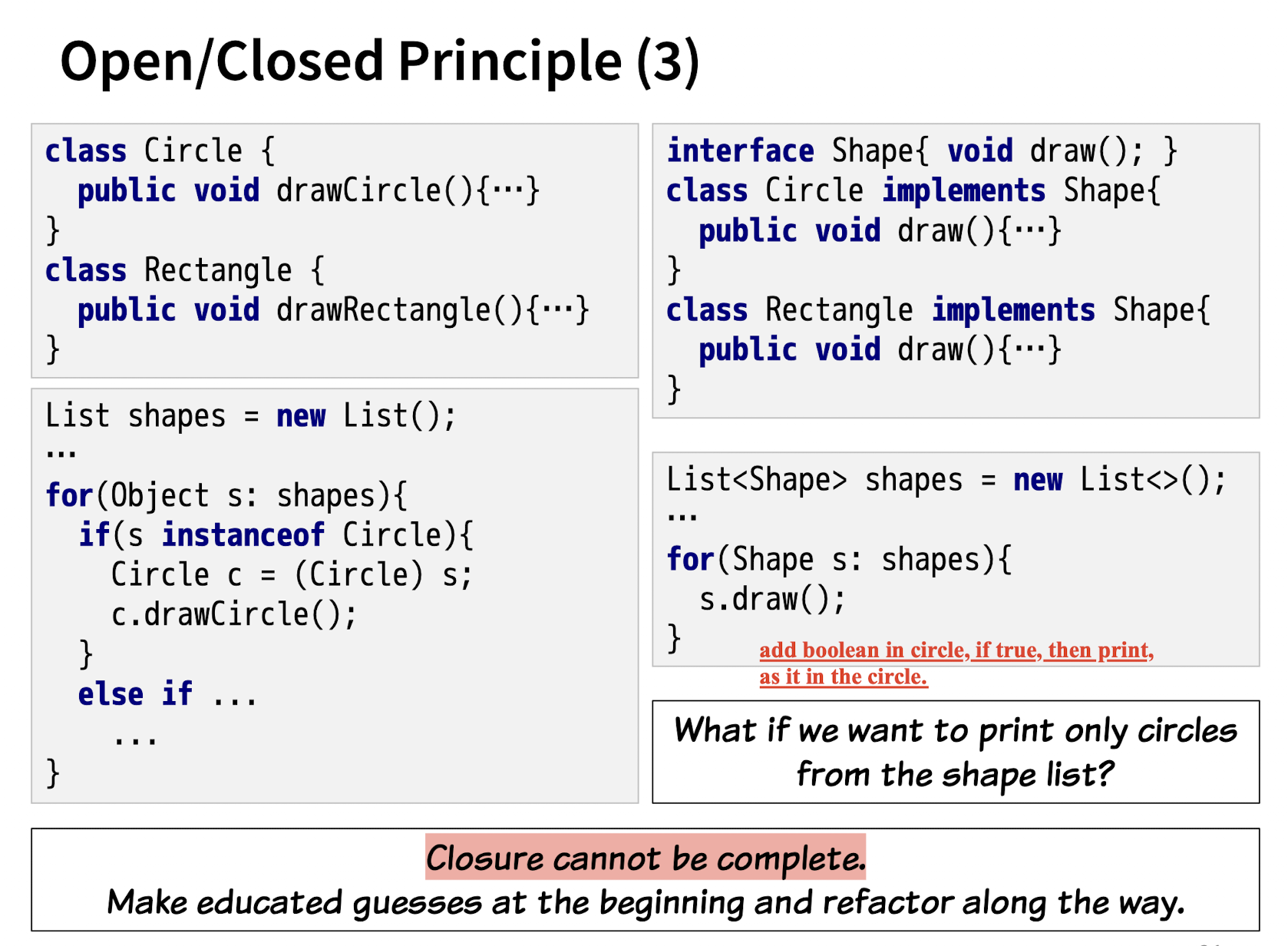
8.3.2 Open/Closed Principle
Software entities should be open for extension (good for inheritance)
but closed for modification.(modification should not be open to clients)
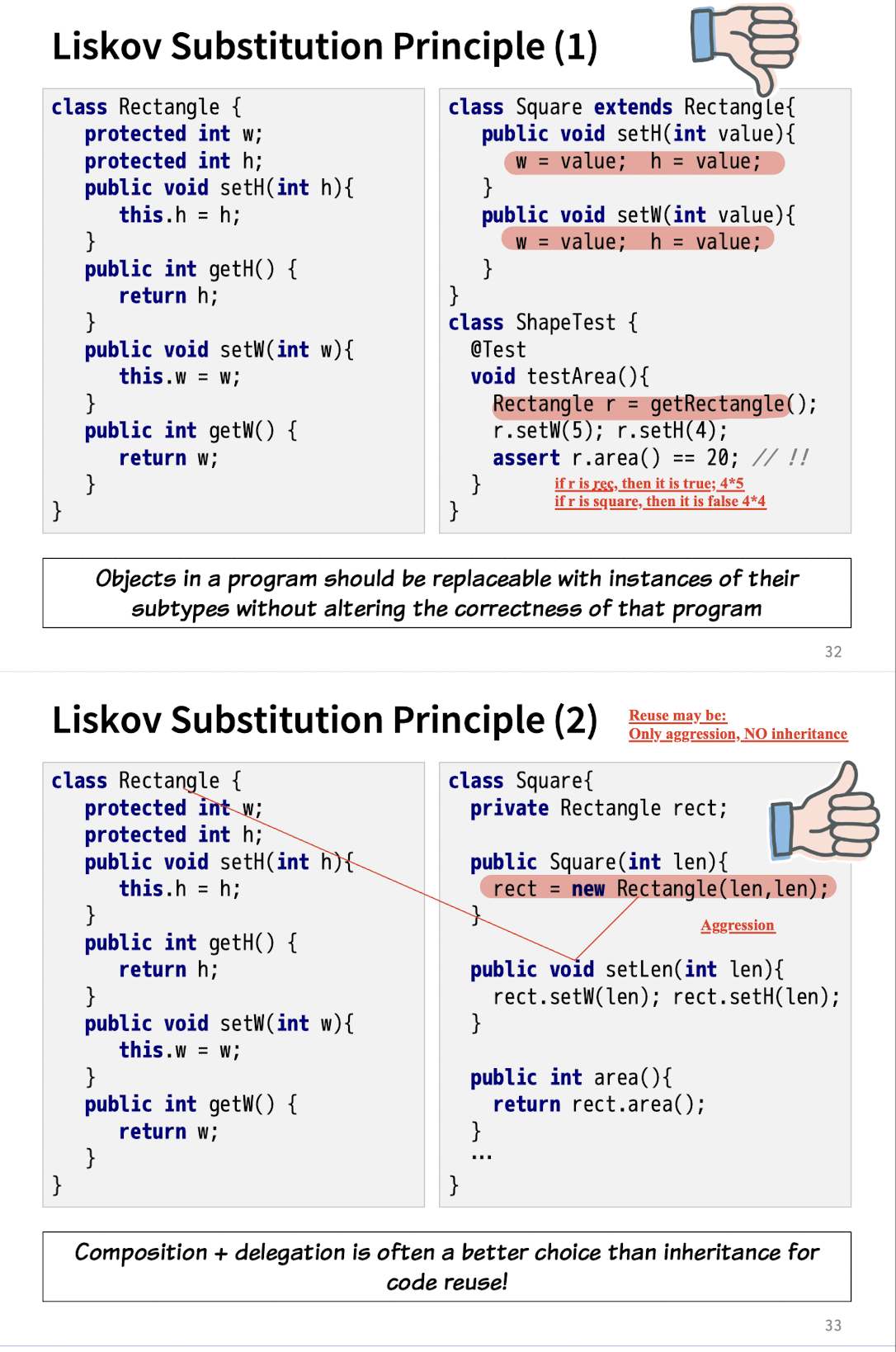
8.3.3 Liskov Substitution Principle
Objects in a program should be replaceable with instances of their subtypes without altering the correctness of that program
8.3.4 Interface Segregation Principle
Many client-specific interfaces(small) are better than one general-purpose(big) interface.
One interface for each responsibility.
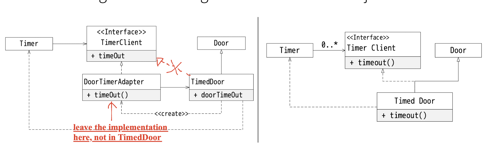
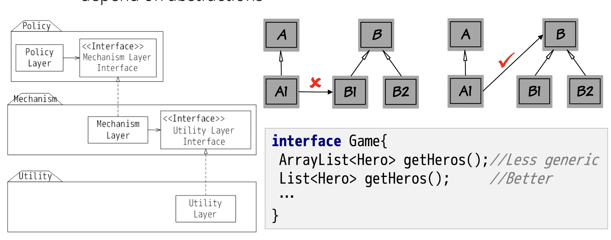
8.3.5 Dependency Inversion Principle
Limited reusability of the higher-level components
High-level modules should not depend on low-level modules. Both should depend on abstractions(interface);
Abstractions should NOT depend on details. Details should depend on abstractions.
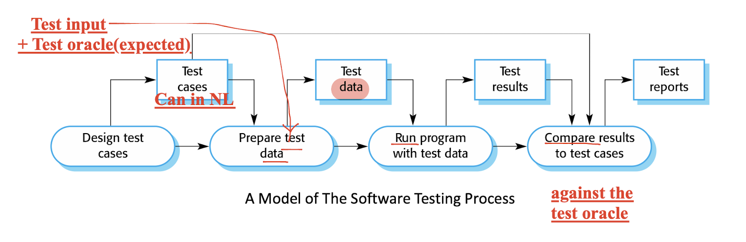
9 Software Testing
Test:
- to show that a program does what it is intended to do
- to discover program defects before it is put into use.
- Using artificial data to test, not fake data
- to check
- errors, anomalies or
- information about the program’s non-functional attributes(performance…).
- ONLY know the presence of errors but NOT their absence.
Goals:
- Show the software meets its requirements (Validation test);
- Use the data that reflect the system’s expected use (Correct data).
- For custom software, one test for every requirement;
- For generic software, tests for all of the system features, plus combinations of these features
- Discover defects and incorrect (Defect test).
- Use the data that obscure or incorrect, which need not reflect how the system is normally used.
- Extreme case like, Integer.MAX_VALUE;
Verification & Validation (V&V)
- Verification:
- On specification, which build by the developer team;
- Validation:
- On the user’s real requirement, which build by the user team;
- Goal: establish confidence that the system is ‘fit for purpose’.
- Software purpose: How critical it is;
- User expectation: low expectations of certain kinds of software.
- Marketing environment: early release may be more important than finding defects in the program.
Software Inspections:
- Technique for V\&V;
- The aim of discovering anomalies and defects;
- Benefits:
- be applied to any representation of the system (requirements, design, configuration data, test data, etc.).
- During testing, errors can mask (hide) other errors;
- inspection is a static process, you don’t have to be concerned with interactions between errors.
- broader quality attributes of a program, such as compliance with standards, portability and maintainability.
Stages of Testing:
- Development testing: discover bug and defect;
- Release testing: separate testing team test a complete
version od the system, before the release to users; - User testing: Users or potential users involved in the test;
9.1 Development Testing
Most of them are primarily a defect testing process.
- Unit Testing
- Component Testing
- System Testing
White box testing vs. black box testing
- White: See inside the system;
- Unit test;
- Black: do not inside the box, only know the iuput and output of the system. (No need to know the detailed implementation of the system);
- Component test;
- System test;
9.1.1 Unit Testing
- Test on the object classes
- On the functionality of the individual classes;
- Test in isolation;
- Primarily a defect testing process.
Subject of test:
- Individual functions or methods within an object
- Object classes with several attributes and methods;
- Getter and setter;
- All the operations of the class;
- Try the object in possible different state, like internal state in boolean;
- with Simulating all events that cause a state change.
Drawbacks:
- When using inheritance, some field may NOT be localized, may be depended on the super class;
Automated Testing
- Can run and checked without manual intervention.
- Using test automation framework (such as JUnit)
- setup part: initialize inputs and expected outputs.
- call part: call the object or method to be tested.
- assertion part: compare the result of the call with the expected result;
Two types of Unit test cases:
- Case that normal operation;
- Case where common problems arise;
Testing Strategies:
Partition Testing:
- Identify the input having same behavior or characteristic;
- Input from a same partition should be identical;
- Partition based on the input requirements; As well as the requirements on the coverage;
Testing Guidelines:
- Software with sequences:
- have only a single value.
- different sizes in different tests.
- Derive tests so that the first, middle and last elements of the sequence are accessed.
- sequences of zero length.
- General software:
- Choose inputs that force the system to generate all error messages
- cause input buffers to overflow;
- Repeat the same input or series of inputs numerous times;
- Force computation results to be too large or too small.
- Software with sequences:
9.1.2 Component Testing
- Units are integrated into components;
- On the components’ interfaces;
- Made up of several interacting objects;
- Access the each the object indirectly through the component’s interface; like black box;
- Check the behavior of the interface;
Interface Testing
- Goal: detect faults due to interface errors or invalid assumptions about interfaces.
- 4 types of interface:
- Parameter interfaces.
- Data passed from one method or procedure to another.
- Shared memory interfaces.
- Block of memory is shared between procedures or functions.
- like, global variable; read and write on the variable;
- Procedural interfaces.
- Sub-system encapsulates a set of procedures to be called by other sub-systems.
- Like,
- Message passing interfaces.
- Sub-systems request services from other sub-systems.
Interface Errors:
- Interface misuse
- error in its use of its interface e.g. parameters in the wrong order.
f(int),f(String)
- error in its use of its interface e.g. parameters in the wrong order.
- Interface misunderstanding
- behaviour of the called component which are incorrect.
- Timing errors
- at different speeds and out-of-date information is accessed.
Interface Testing Guidelines
- stress testing
- …
9.1.3 System Testing
- All or some of the components are integrated into a system;
- Test as a whole;
- On the components’ interfaces;
- Two important key, even though overlap with the component test:
- The complete system is tested.
- System testing is a collective
- Component testing may be individual.
Testing Policies
- Exhaustive system testing is impossible;
- required system test coverage may be developed.
- When to stop the testing;
- Policies:
- Functions accessed through menus should be tested;
- Combinations of functions (e.g., text formatting) that are accessed through the same menu must be tested;
- On user input is provided, all functions must be tested with both correct and incorrect input.
9.2 Test-Driven Development
TDD
- Tests are written before code and ‘passing’ the tests is the critical driver of development.
- You develop code incrementally, along with a test for that increment. You don’t move on to the next increment until the code that you have developed passes its test.
Benefits
- Code coverage: All code written has at least one test.
- Regression testing: A regression test suite is developed incrementally as a program is developed.
- Simplified debugging: When a test fails, it should be obvious where the problem lies. The newly written code needs to be checked and modified. (easy to locate)
- System documentation: The tests themselves are a form of documentation that describe what the code should be doing.
Regression Testing
- testing the system to check that changes have not ‘broken’ previously working code.
- Tests must run ‘successfully’ before the change is committed.
(Change must pass test first)
9.3 Release Testing
testing a particular release of a system that is intended for use outside of the development team.
Validation testing;
- to convince the supplier of the system that it is good enough for use.
- black-box testing process
Release Testing vs System Testing
- Release testing is a form of system testing.
- Use in Release testing:
- Requirements-based testing
- Scenario testing
- Different:
- separate team in release testing, NOT in system testing;
- Discovering bug is in System testing, NOT in release testing;
- Release testing: meets its requirements and is good enough for external use (validation testing).
Performance Testing
- performance and reliability
- Performance tests: planning a series of tests where the load is steadily increased until the system performance becomes unacceptable. (try the limit)
- Stress testing: a form of performance testing where the
system is deliberately overloaded to test its failure behavior. (we know system can not take it.)
9.4 User Testing
From the user, out side of the develop team;
users or customers provide input and advice on system testing.
- Essential than system and release testing have been carried out.
- influences from the user’s working environment have a major effect on the reliability, performance, usability, and robustness of a system.
Types of User Testing
- 1. Alpha testing
- Users are involved, but still inside the develop team; from their site;
- 2. Beta testing
- open to users to allow them to experiment with the software
1 and 2 on how test performed.
- 3. Acceptance testing
- On what the purpose of the tests are;
- whether or not it is ready to be accepted from the system developers and deployed in the customer environment.
The Acceptance Testing Process
- Agile Methods and Acceptance Testing
- User are with the develop team; for making decisions;
- So NO separate acceptance testing process.
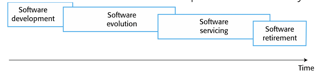
10 Software Evolution
Software change:
- inevitable
- Error correction;
- Performance improvement;
- Business environment change;
- New equipment added;
Software evolution: - As the critical business assets.
- maintain the value;
- changing and evolving existing software rather than build a new one;
Four stages: - Development: water fall,…
- Evolution: new requirements are proposed and implemented in the system;
- Servicing:
- remains useful;
- only changes made are those required to keep it operational(bug fix,…)
- NO new function is added;
- Retirement:
- remains useful;
- only essential changes; if no change, then not useful;
- Users have to work around problems that they discover.
10.1 Evolution Processes
- Depend on
- type of software(bank, mobile app,…);
- development processes;
- skills and experience of the people()
Reasons of Evolution - Proposals for change are the driver for system evolution.
- bug reports;
- adaptation to the new environment
- new ideas for software improvement
- new requirements
10.1.1 General Model
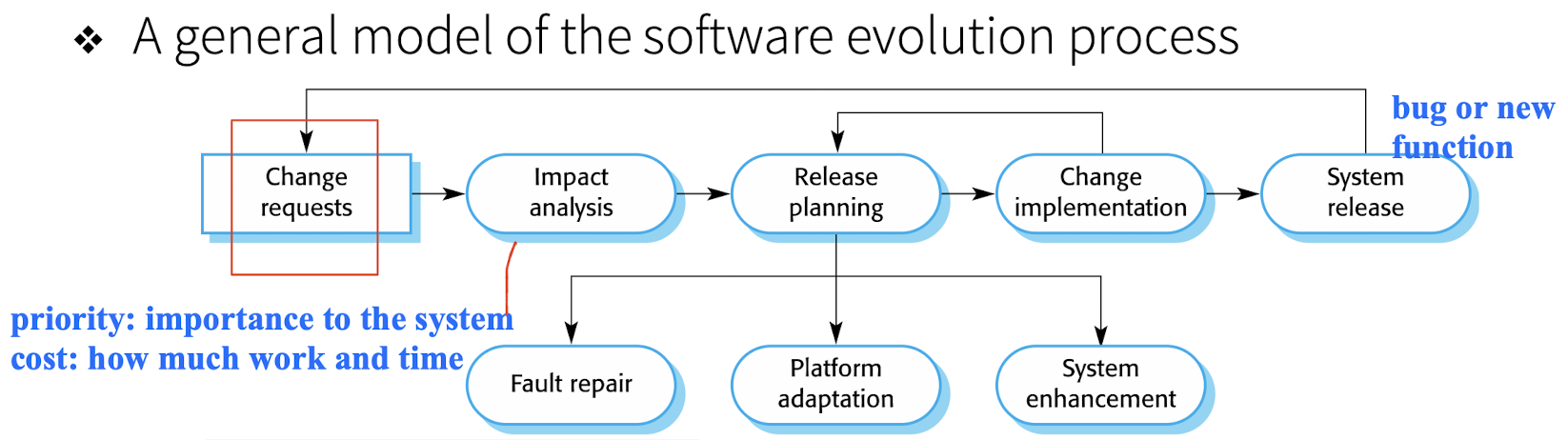
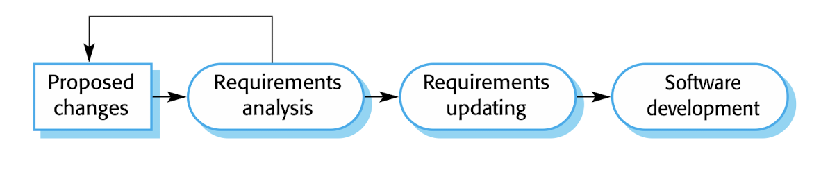
Change implementation:
- Different between Development and Evolution;
- that the first stage of change implementation may involve program understanding
10.1.2 Urgent Change Requests
General change implementation need few days, take sime time.
While it is too slow in urgent change requests.
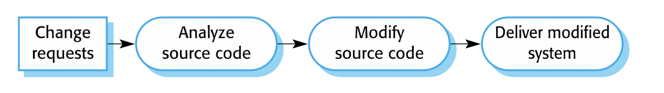
- faster!! Without going through all stages of the software evolution process
10.1.3 Agile Methods and Evolution
Agile methods are based on incremental development so the transition from development to evolution is a seamless one(perfect, evolution friendly).
- Evolution is simply a continuation of the development process
- Automated regression testing is particularly valuable when changes are made to a system.
Problems: - comes from the inside of the team;
- 1.development team: agile approach, but the evolution team: plan-based approach
- No sufficient documentation in development;
- 2.development team: plan-based approach, but the evolution team: agile approach
- Agile has comprehensive tests, but mat not enough in the development
10.2 Software Maintenance
Modifying a program after it has been put into use.
- Focus on the custom software
- NOT normally involve major changes to the system’s architecture.
- DO modifying existing components and adding new components to the system.
Three types(based on the reason of maintenance):
- Fault repairs (bug reports)(!!)
- Environmental adaptation (new environment)(!)
- Functionality addition and modification (new requirements)(!!!)
10.2.1 Maintenance Costs
greater than development costs (X2 ~ X100)
- Cost is increased while Maintenance;(harder and harder to change the system);
- more expensive to add new features to a system during maintenance than it is to add the same features during development
- Reason:
- maintenance work is unpopular: inexperienced and have limited domain knowledge;
- NO incentive(motivation) for the development team to write maintainable software;
- New team has to understand the programs being maintained;
- As programs age, their structure degrades, and they become harder to change.
10.2.2 Maintenance Prediction
To reduce the cost of maintenance.
Assessing which parts of the system may cause problems and have high maintenance costs;
Using:
- Complexity and process data(more is harder to maintain);
- Predicting the number of change requests;
- relationship between the system and its external environment.
- Predicting information about change requests
10.2.3 Software Reengineering
- Restructuring or rewriting part or all of a legacy system
- WITHOUT changing its functionality—to make them easier to maintain.
- Good for some but not all sub-systems of a larger system require frequent maintenance.
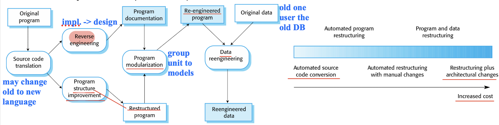
Why needed? The advantage of Reengineering over replacement:
- Reduced risk
- Reduced cost(Reengineering is cheaper then from beginning)
cost factoexpert staff for reengineering. rs:
- quality of the software to be reengineered.(itself should be good, easy to reengineer);
- tool support available;
- extent of the data conversion which is required;
- expert staff for reengineering;
Limitation:
- Converting the programming paradigm is impossible(so hard);(POP -> OOP)
- Major architectural or data management changes are expensive;
- resulting system probably is not as maintainable as a new system;(not worth it)(less freedom in reengineering)
10.2.4 Refactoring
process of making improvements to a program to slow down degradation through change.
- NOT add functionality but rather concentrate on program improvement. AS preventative maintenance;
Refactoring vs Reengineering:
- How often they performed;
- Refactoring: continuous process of improvement; any time you want;
- more on single model
- On legacy or new system
- Reengineering: after a system has been maintained for some time and maintenance costs are increasing,
- More on the whole system;
- it is limited;
- Only on the legacy
10.2.5 Bad Smells in Program Code
Stereotypical situations where the code of a program can be improved
- Not bugs;
- But it will make the system hard to understand or maintain;
Examples:
- Duplicate code;
- Long methods should be redesigned as a number of shorter methods;
- Switch(case) statements that depend on value types can often be replaced with polymorphic code in object-oriented languages;
- Data clumping: re-occurring groups of data items can often be replaced with an object that encapsulates all of the data. (put them into class with filed and method)
- Speculative generality: required in the future, can often simply be removed. (Remove the over design for the future)
10.3 Version Management
process of keeping track of different versions of software components or configuration items and the systems in which these components are used.
!!! note Ensuring that changes made by different developers to these versions do not interfere with each other.
- the process of managing codelines and baselines.
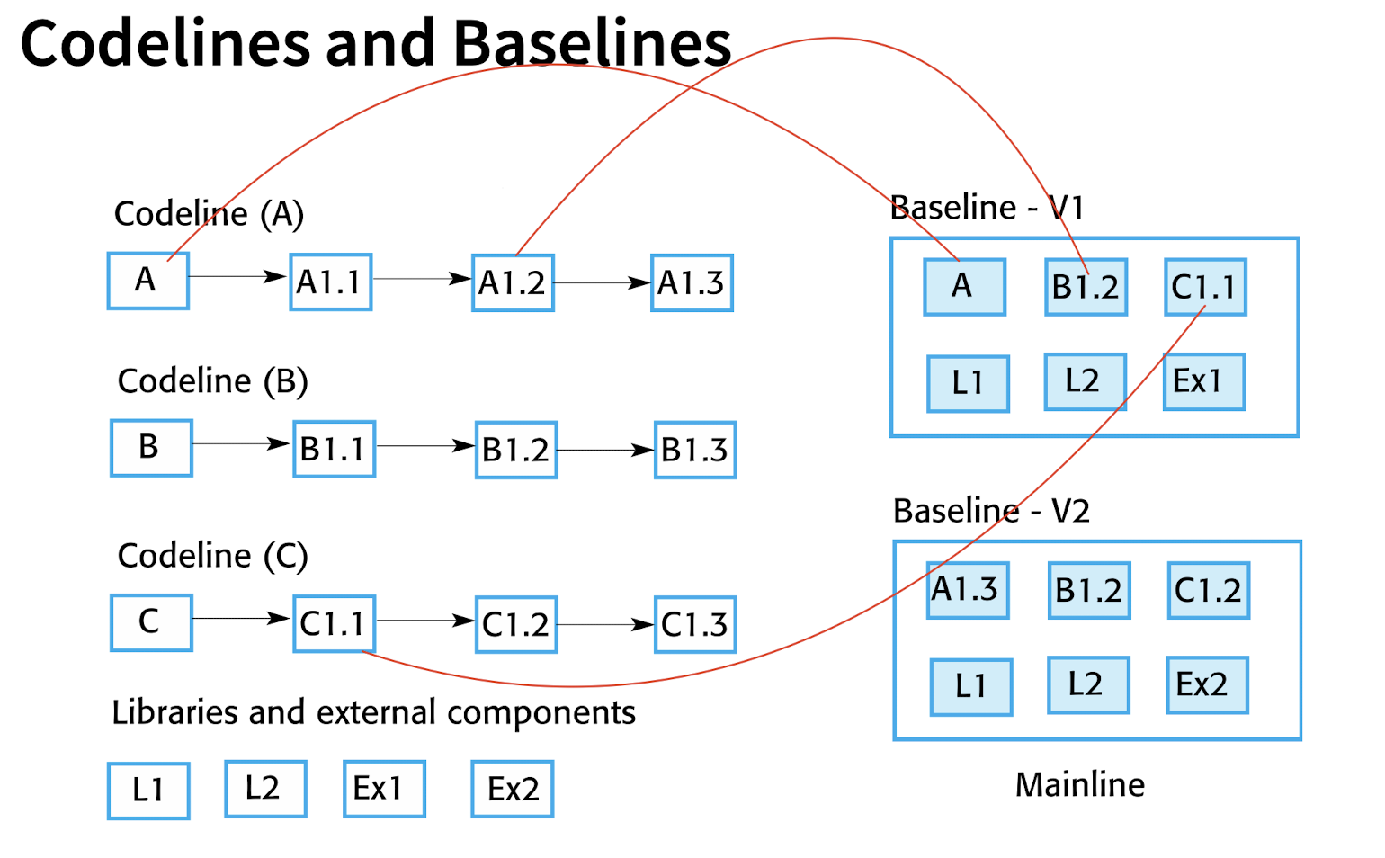
10.3.1 Codelines and Baselines
Codelines:
- sequence of versions of source code
Baseline:
- specifies the component versions that are included in a specific system and the libraries and configuration files
- Collection of the components that make up a system at a particular point in time.
10.3.2 Version Control Systems
identify, store and control access to the different versions of components
Five Features of Version Control Systems:
- Version and release identification:
- Identify and manage the versions(baseline);
- Change history recording:
- Support for independent development:
- How work with VCS
- independent development
- Project support
- Storage management
Centralized systems:
- a single master repository that maintains all versions of the software components that are being developed.
Distributed systems:
- multiple versions of the component repository
Version control systems vs. cloud storage systems
- VCS;
- Contains multiple changes;
- To help to merge the changes
- CSS:
- Totally overwrite the old version, like Google Drive;
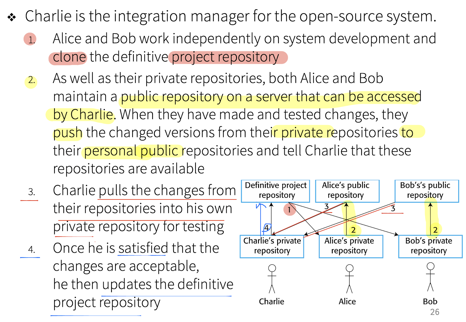
10.3.3 Project Repository and Private Workspace
Project repository:
- project repository maintains the ‘master’ version of all components, which is used to create baselines for system building.
- When modifying components, developers copy (check-out) these from the repository into their workspace and work on these copies.
- When they have finished their changes, the changed components are returned (checked-in) to the repository.
Centralized vs. distributed
- In centralized version control, a private workspace contains only components from the project repository.
- Only check out the data we want;
- In distributed version control, a private workspace is a clone of the project repository.
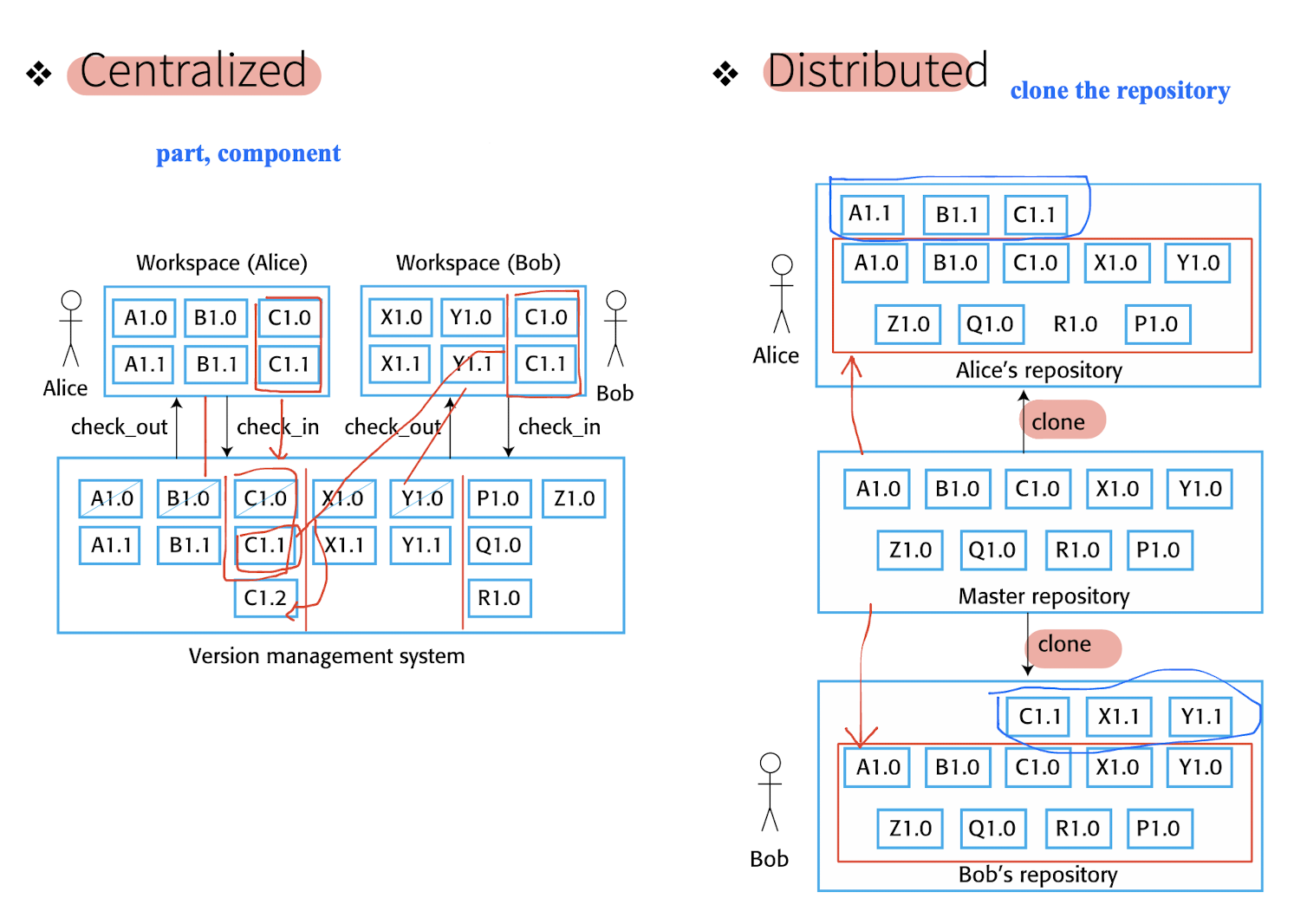
Benefits of Distributed Version Control
- provides a backup mechanism for the repository;
- off-line working so that developers can commit changes if they do not have a network connection.
- Check-in require network connection in centralized VCS;
- Project support is the default way of working.
- essential for open-source development.
10.3.4 Organization of Open-Source Development
10.3.5 Branching and Merging
- Rather than a linear sequence of versions that reflect changes to the component over time, there may be several independent sequences.
- Branch:
- Avoid to interfere with each other;
- Merge:
- merge codeline branches to create a new version of a component that includes all changes that have been made.
- Improve the flexibility of the VCS; when new idea coming in;
10.3.6 Storage Management
- Instead of keeping a complete copy of each version, the system stores a list of differences (deltas) between one version and another, because disk space was expensive. (Centralized VCS)
- Drawback:
- Difficult to get the least version of the code; find from the first version from beginning;
- chain of operations.
In Git:
- (Distributed VCS)
- Git does NOT use deltas but
- applies a standard compression algorithm to stored files and their associated meta-information.
- does not store duplicate copies of files.
- simply involves decompressing it, with no need to apply a chain of operations.
10.4 Legacy Systems
Older systems that rely on languages and technology that are NO longer used for new systems development.
Problems:
- structure may have been degraded;
- depend on older hardware and may have associated legacy processes and procedures;
- NOT just software systems but are broader socio-technical systems that include hardware, software, libraries and other supporting software and business processes.
- Older hardware has bad interface;
- Police different;
- …
11 Software Reuse
Library, Class, Packages,…
To a design process that is based on systematic software reuse
Less change to build a new system from scratch
Types of reuse:
- System reuse: Complete systems, which may include several application programs may be reused.
- Application reuse: An application may be reused either by incorporating it without change into other or by developing application families.
- Component reuse: Components of an application from sub-systems to single objects may be reused.
- Object and function reuse: Small-scale software components that implement a single well-defined object or function may be reused.
Benefits
- Accelerated development
- Effective use of specialists
- Increased dependability
- Lower development costs
- Reduced process risk (less code less risk)
- Standards compliance (like GUI, increase the user friendliness)
Problems
- Creating, maintaining, and using a component library
- (hard than only develop a solution to a problem not for further reusing)
- Finding, understanding, and adapting reusable components
- not easy to find the right library
- Increased maintenance costs
- use for a long time;
- Lack of tool support
- Not-invented-here syndrome
- All want to code by themselves, but not good, they should use the library;
11.1 Reuse Landscape
- Some Approaches That Support Software Reuse
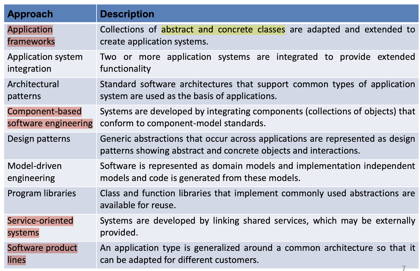
- Reuse Planning Factors
- The development schedule for the software.
- More time: from scratch; Less time: from library;
- The expected software lifetime.
- The background, skills and experience of the development team.
- Having good understanding of the library; having skill on the framework, know how to optimize the using;
- The criticality of the software and its non-functional requirements.
- The application domain.
- The execution platform for the software.
- OS, hardware, etc.
- The development schedule for the software.
11.2 Application Frameworks
- A collection of a generic structure that is extended to create a more specific subsystem or application
- Like, having a already MVC framework, we can extends the MVC parts, (Like extends View, extends Controller, extends Model)
- support for generic features that are likely to be used in all applications of a similar type
- support design reuse in that they provide a skeleton architecture for the application as well as the reuse of specific classes in the system.
11.2.1 Web Application Frameworks (WAFs)
WAFs are now available for all the commonly used web programming languages.
- Support the construction of dynamic websites as a front-end for web applications.
11.2.2 Extending Frameworks
Frameworks are generic and are extended to create a more specific application or sub-system. They provide a skeleton architecture for the system.
Ways:
- Adding concrete classes that inherit operations from abstract classes in the framework;
- Adding (callback) methods that are called in response to events that are recognized by the framework.
- Not meant to be called;
- Not be directly called, but will be registered and called when necessary; (keep track of what methods should be called)
- Often to handle events;
- e.g.:
- (onClick={xxx} in JS)
- interface X {
void f();
} - When a button is clicked, List
Xs, each x.f() will be called; - Through
addOnClickHandler(X x){xs.add(x)}
Problems:
- One problem with frameworks is their complexity which means that it takes a long time to use them effectively.
- Code is less, but how to use is not easy;
11.3 Software Product Lines
When a company has to support a number of similar but not identical systems, one of the most effective approaches to reuse is to create a software product line.
A software product line is a set of applications with a common architecture and shared components, with each application specialized to reflect different requirements.
Adaptation to the new system:
- 1.Selecting from a library of existing components;
- 2.Component and system configuration;
- 3.Modifying components to meet new requirements.
- 4.Adding new components to the system;
11.3.1 Base Systems
- Usually emerge from existing applications. Not from scratch;
Involve:
- identifying common functionality in product instances and
- developing a base application, which is then used for future development.
Three types of the base system:
- Core components: infrastructure support.
- Configurable components: may be modified and configured to specialize them to a new application.
- Specialized, domain-specific components: some or all of which may be replaced when a new instance of a product line is created.
11.3.2 Application Frameworks and Product Lines
Common:
- support a common architecture and components
- require new development to create a specific version of a system.
Diff.:
- Application frameworks:
- 1.OOP (like, polymorphism to implement extension)
- 2.general rather than domain-specific support
- 3.often software-oriented.
- Software product lines:
- 1.May NO need on OOP
- 2.embed domain and platform information;
- 3.often control applications for equipment;
- made up of a family of applications, usually owned by the same organization.
11.3.3 Product Line Architectures
reflects a general, application-specific architectural style or pattern.
Specialization of A Software Product Line
- Platform specialization. Versions of the application may be developed for different platforms.
- Environment specialization. Versions of the application may be created to handle different operating environments and peripheral devices.
- Functional specialization. Versions of the application may be
created for specific customers who have different requirements. - Process specialization. The system may be adapted to cope with specific business processes.
11.3.4 Product Instance Development
- Elicit stakeholder requirements
- Use an existing family member as a prototype
- Choose a closest-fit family member(similar user)
- Find the family member that best meets the requirements
- Re-negotiate requirements
- Adapt requirements as necessary to the capabilities of the software
- Adapt the existing system
- Develop new modules and make changes for the family member
- Deliver the new family member
- Document key features for further member development
11.3.5 Product Line Configuration
- Design time configuration:
- Modifying a common product line core by developing, selecting or adapting components to create a new system for a customer.
- Deployment time configuration
- generic system is designed for configuration by a customer or consultants working with the customer;
- Knowledge of the customer’s specific requirements and the system’s operating environment is embedded in the configuration data used by the generic system. (user choose and OS option is already in the generic system);
11.4 Component-Based Software Engineering
(CBSE)
Single class is not easy for reusing, for it depends on other classes.
- An approach to software development that relies on the reuse of entities called “software components”.
- emerged from the failure of object-oriented development to support effective reuse. Single object classes are too detailed and specific.
- Components are more abstract than object classes and can be stand-alone service providers.
Key points:
- Independent components specified by their interfaces.
- Only how to use,no need know the implementation;
- Component standards to facilitate component integration.
- In some standards, for communication
- Middleware that provides support for component inter-operability.
- A development process that is geared to reuse.
11.4.1 Component Characteristics
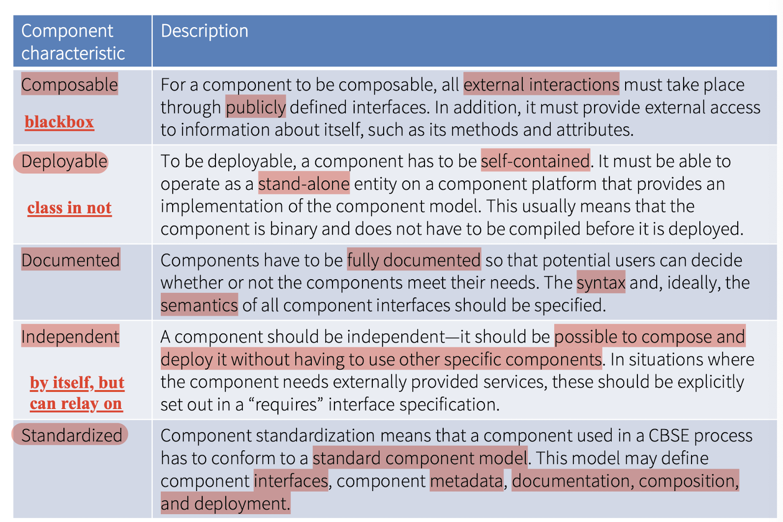
11.4.2 Components As Providers of Services
A useful way of thinking about a component is as a provider of one or more services,
- have two related interfaces:
- The “provides” interface defines the services provided by the component.
- The “requires” interface specifies the services that other components in the system must provide if a component is to operate correctly.
11.4.3 Component Models
A component model is a definition of standards for component implementation, documentation, and deployment.
Basic elements of a component model
- Interfaces: How the interfaces should be defined and what elements should be included in the interface definition.
- Usage: How the components should be addressed.
- Deployment: How components should be packaged for deployment as independent, executable entities
Component Model Implementation
provides:
- Platform services that enable components to communicate and interoperate in a distributed environment;
- Support services that are application-independent services used by different components.
- Needed bu different components;
Components can be considered as being deployed in containers
- A container is an implementation of these services plus a definition of the interfaces that a component must provide to integrate it with the container.
- Execution environment for a component for communication and interoperation with other components.
11.4.4 CBSE Processes
CBSE processes are software processes that support component-based software engineering.
- Development for reuse: Process concerned with developing components or services that will be reused in other applications;
- Development with reuse: Process of developing new applications using existing components and services;
11.5 Service-Oriented Software Engineering
Service-oriented SE is a way of building distributed applications using web services.
- Web service is a loosely coupled, reusable software component that encapsulates discrete functionality, which may be distributed and programmatically accessed.
- Much more flexible, like HTTP, …
- High level of independence;
Service-oriented SE vs. Component-based SE:
- When you build a service-oriented system, you reference the external service; Each system that reused a component had to incorporate its own copy of that component.
- Services should always operate in the same way, irrespective of their execution environment; Components may have a “requires” interface that defines the other system components that must be present;
Benefits:
- Services can be offered by any service provider inside or outside of an organization.
- The service provider makes information about the service public so that any authorized user can use the service.
- Applications can delay the binding of services until they are deployed or until execution.
- loosely coupled
- can choose which service at run time;
- flexible
- Opportunistic construction of new services is possible.
- Service users can pay for services according to their use rather than their provision.
- Applications can be made smaller, which is particularly important for mobile devices with limited processing and memory capabilities.
References
I. Sommerville, Software engineering, 10th ed. Boston, Mass. Amsterdam Cape Town Pearson Education Limited, 2016.
Slides of COMP3211 Software Engineering, The Hong Kong Polytechnic University.
个人笔记,仅供参考,转载请标明出处
PERSONAL COURSE NOTE, FOR REFERENCE ONLY
Made by Mike_Zhang